Fuel reforming system

A reforming system and fuel reformer technology, applied in fuel cells, fuel cell additives, inorganic chemistry, etc., can solve problems such as inability to install evaporators, space limitations, etc.

Inactive Publication Date: 2002-12-04
NISSAN MOTOR CO LTD
View PDF0 Cites 12 Cited by
  • Summary
  • Abstract
  • Description
  • Claims
  • Application Information

AI Technical Summary

Problems solved by technology

[0024] Such an evaporator may be used in fuel reforming systems for stationary fuel cells, but space constraints prevent installation of such evaporators in mobile fuel cell fuel reforming systems

Method used


Image

  • Fuel reforming system
  • Fuel reforming system
  • Fuel reforming system

Examples


Embodiment Construction

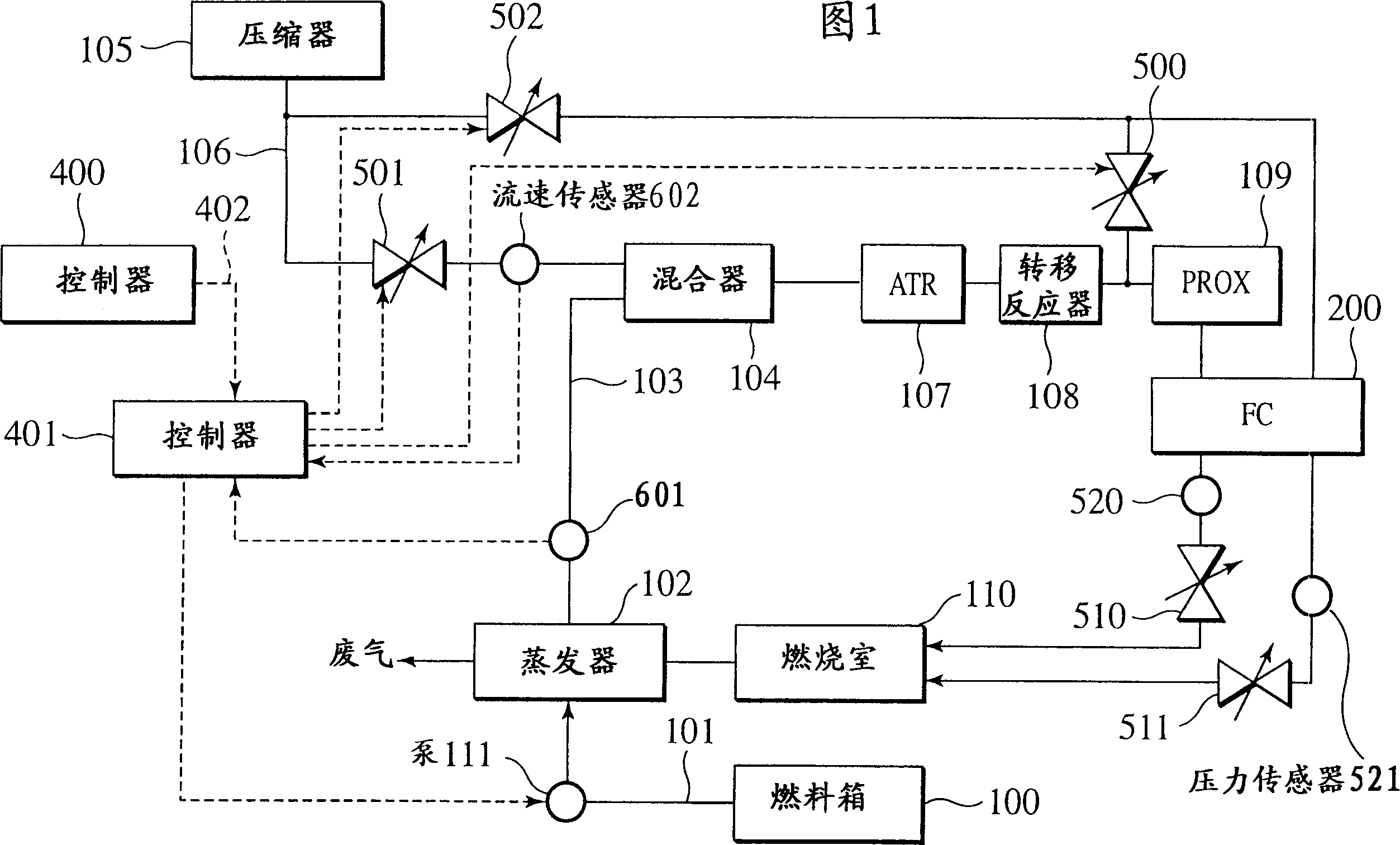
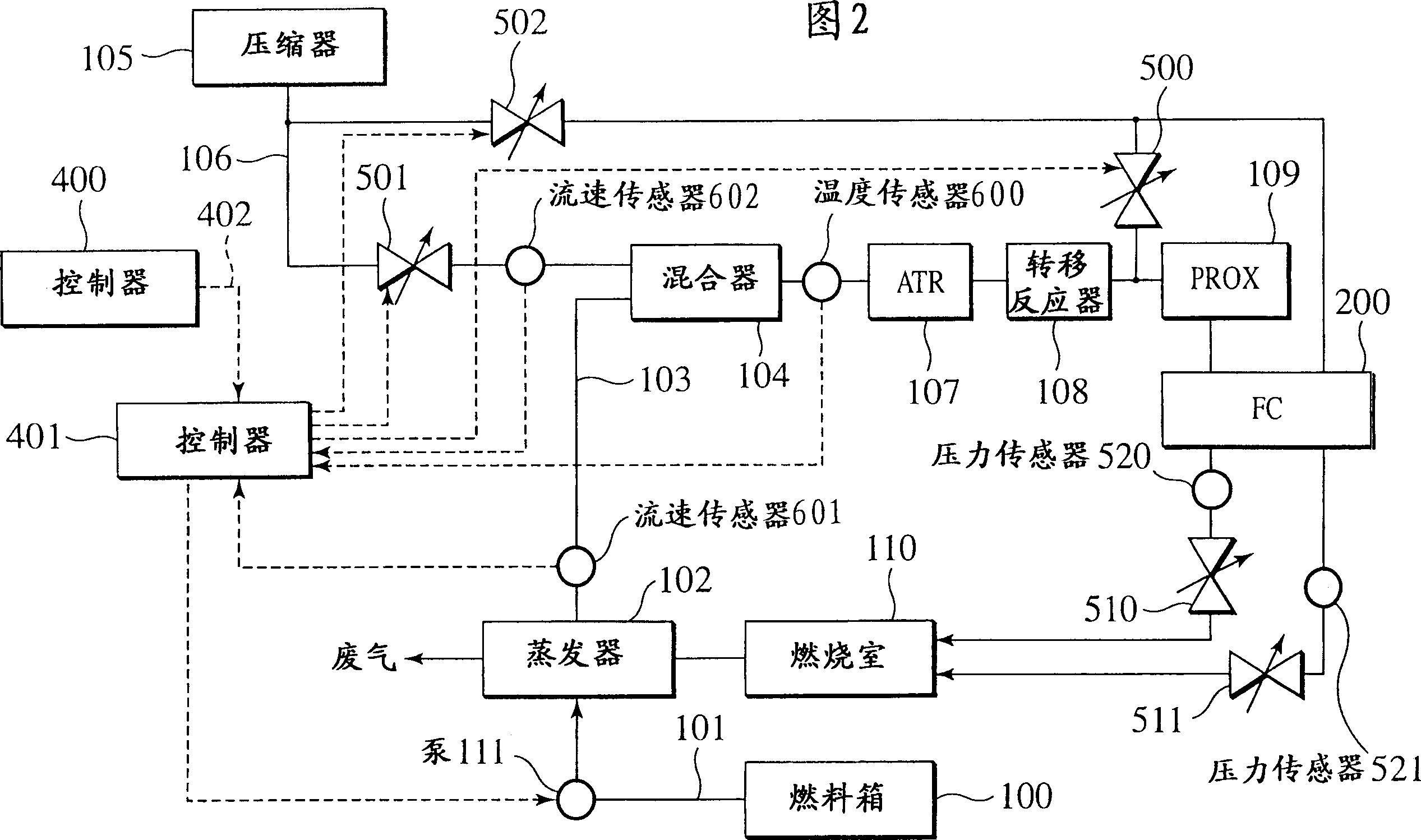
[0043] The fuel reforming system in the first embodiment will be described with reference to FIGS. 2 to 7 . The fuel reforming system of the first embodiment shown in FIG. 2 is characterized in that a temperature sensor 600 is introduced to detect the temperature of the mixture to be sent to an autothermal reforming reactor 107, and the output of the temperature sensor 600 is transmitted to the fuel reforming reactor 107. whole controller 401. In FIG. 2 , the same reference numerals are used for the same components as those of the prior art shown in FIG. 1 .

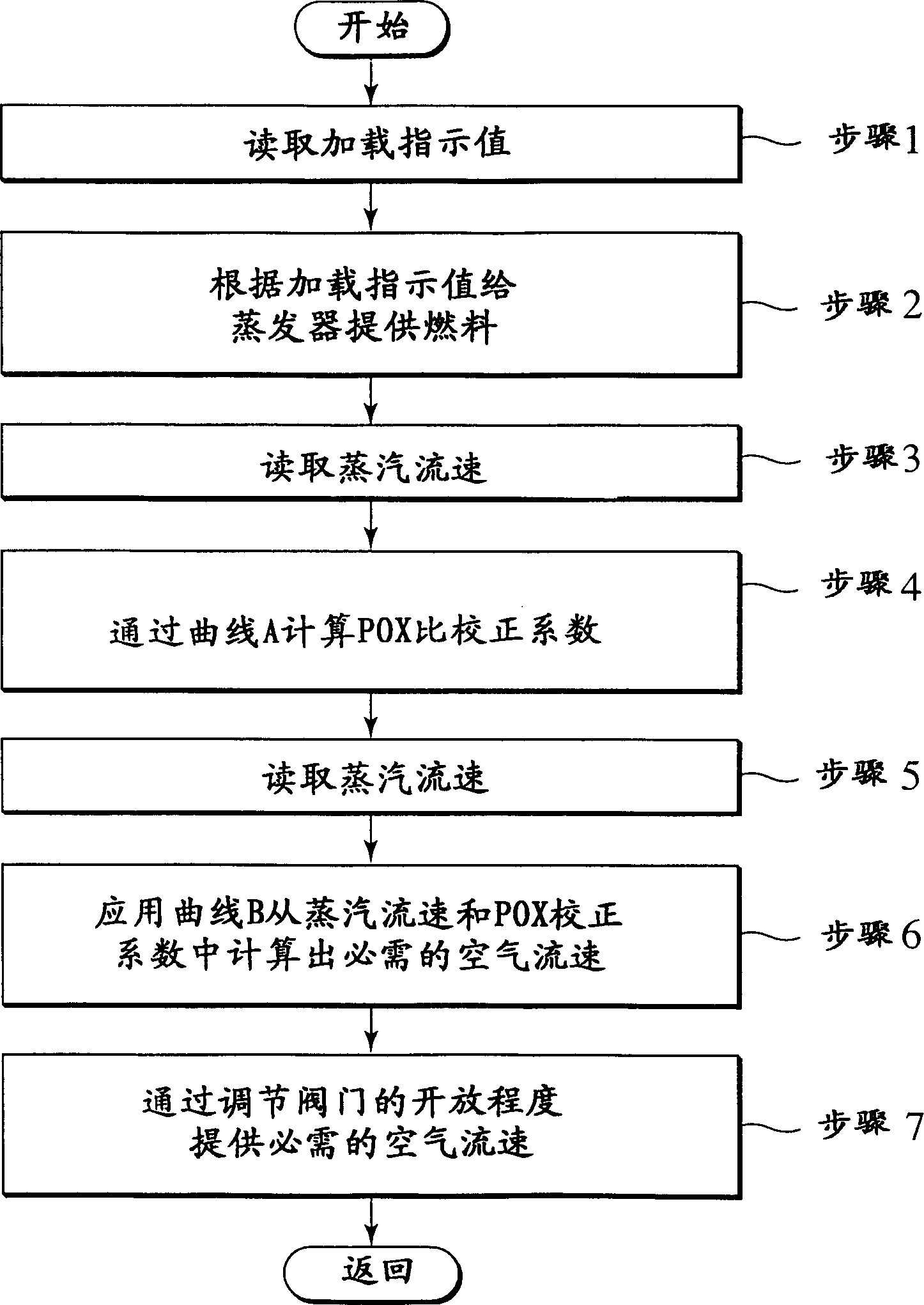
[0044] The control sequence of the fuel reforming controller 401 of the fuel reforming system refers to image 3 Be explained.

[0045] Step 1: The fuel reforming controller 401 reads a work load signal 402 of the fuel reforming system transmitted from the controller 400;

[0046] Step 2: the fuel reforming controller 401 controls the pump 111 according to the duty loading signal 402, and provides a necessary flow rate...


PUM


Abstract

The invention provides a fuel reforming technology applicable to a mobile fuel cell system. Even if the temperature of the steam supplied from the evaporator 102 to the fuel reformer 107 varies significantly, a reformed gas composition usable in the fuel cell 200 can be obtained using this technique. The system includes: flow rate detecting devices 601, 602 for detecting the flow rate of fuel steam and oxygen to be supplied to the fuel reformer 107; A temperature detection device 600 for at least one of the temperatures of the oxygen mixture. Wherein, the ratio of the flow rate of fuel vapor to the flow rate of oxygen is corrected according to the signal value of the temperature detection device, and oxygen is provided according to the corrected ratio.

Description

Technical field: [0001] The present invention relates to a fuel reforming system in a mobile fuel cell system typified by an automotive fuel cell. Background technique: [0002] Referring to FIG. 1 , this figure depicts a prior art fuel reforming system in a mobile fuel cell system represented by an automotive fuel cell. A mixed solution 101 of water and methanol contained in the fuel tank 100 as fuel is sent to the evaporator 102, and after heating and evaporating, a mixed gasification product 103 of water (water vapor) and methanol is formed, and then the gasification product to mixer 104. Air 106 is also sent from compressor 105 to mixer 104 . The mixed gas 103 and air 106 are mixed in a mixer 104 and then sent to an autothermal reforming reactor (ATR reactor) 107 . [0003] The ATR reactor 107 reforms methanol used as fuel and generates oxygen-enriched reformed gas through a catalytic reaction as shown in Chemical Reaction Equation 1 and Chemical Reaction Equation 2 u...

Claims


Application Information

Patent Timeline
Patent Type & Authority Applications(China)
IPC IPC(8): B01B1/00B01J8/00B01J19/00C01B3/32C01B3/48C01B3/58H01M8/00H01M8/04H01M8/06
CPCB01B1/005B01J8/001B01J19/0006B01J2219/00063B01J2219/00164B01J2219/00198B01J2219/00218B01J2219/00231C01B3/323C01B3/48C01B3/583C01B2203/0244C01B2203/0283C01B2203/044C01B2203/047C01B2203/066C01B2203/0811C01B2203/0822C01B2203/0827C01B2203/0844C01B2203/0866C01B2203/1223C01B2203/1235C01B2203/1276C01B2203/1288C01B2203/142C01B2203/1619C01B2203/1633C01B2203/1638C01B2203/169C01B2203/82H01M8/04373H01M8/04402H01M8/0441H01M8/04425H01M8/04776H01M8/04828H01M8/04992H01M8/0612Y02P20/10Y02E60/50H01M8/06C01B3/32B01B1/00
Inventor 岩崎靖和
Owner NISSAN MOTOR CO LTD
Why Eureka
Try Eureka