Water strainer without power source

A decanter and power technology, which is applied in water/sewage treatment, chemical instruments and methods, biological water/sewage treatment, etc., can solve the problems of large power consumption and complex structure of the decanter, and achieve low cost and simple equipment. , the effect of stable operation

Inactive Publication Date: 2002-12-25
CHONGQING KANGDA ENVIRONMENTAL PROTECTION IND GRP
View PDF0 Cites 17 Cited by
  • Summary
  • Abstract
  • Description
  • Claims
  • Application Information

AI Technical Summary

Problems solved by technology

[0004] The invention solves the problems of large po

Method used


Image

  • Water strainer without power source
  • Water strainer without power source
  • Water strainer without power source

Examples


Embodiment Construction

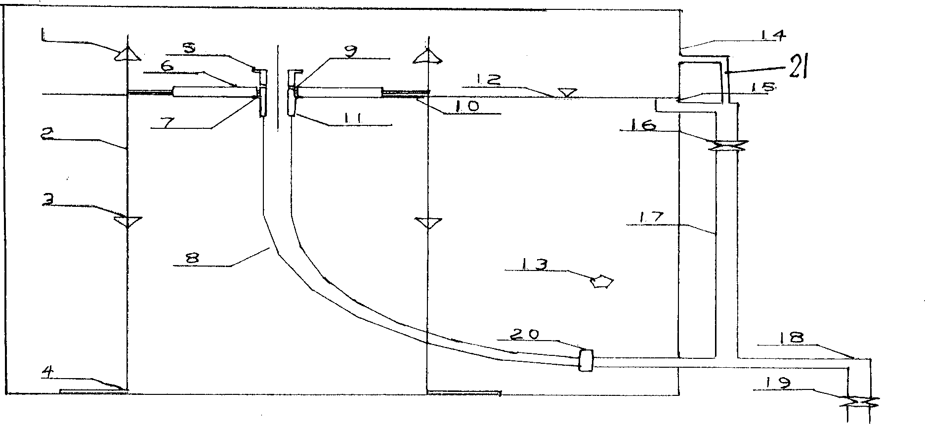
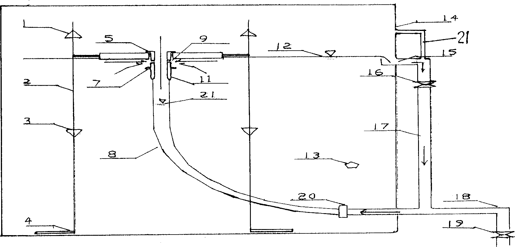
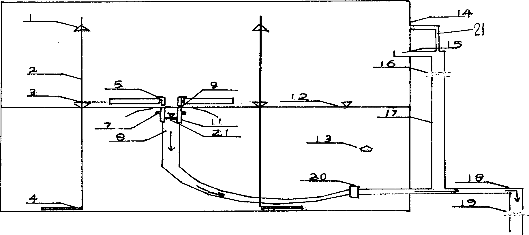
[0026] The non-powered decanter of the present invention has a water collection device on the liquid surface 12, and the water collection device has a float 6 that can float up and down along the vertical guide rail 2. The vertical guide rail is provided with a float upper limit 1 and a float lower limit 3 , The float is connected to the drain pipe 8, the upper part of the drain pipe is connected to the rigid straight pipe 11, the middle part of the rigid straight pipe has a drain port 9, the upper and lower limit devices 5 and the lower limit device 7 are arranged on the upper and lower drain ports, and the drain pipe 8 drains from the bottom of the container through the interface 20 The main pipe 18 is connected, and the main drainage pipe leads to the outside of the container. It is connected to the communication groove 15 on the upper part of the container by the connecting water injection pipe 17. There is an exhaust pipe 21 on the connecting water injection pipe directly lea...


PUM


Abstract

A decanter without power source is composed of a water receiving unit on water surface, a drainage unit and a transmission unit. Said water receiving unit has a float movable along a vertical track with upper and lower limiters and connected to drainage tube which is connected to drainage trunk at bottom of container. A water level sensor is connected to the electromagnetic valves respectively for water pouring tube and drainage trunk. Its advantages are no need of external power unit and sealing, low cost and high running stability.

Description

Technical field [0001] The invention relates to a drainage device, in particular to a decanter. Background technique [0002] In the drainage operation of the variable water level container, the requirements for the decanter are: timely drainage without disturbing the sludge layer. The existing decanter can be divided into mechanical type, automatic type and a combination of mechanical and automatic from the transmission mode, and can be divided into siphon type, hose type, float type and sleeve type from the weir mouth. In terms of form, it can be divided into pontoon type and disc type. At present, the main types of decanters used in the intermittent activated sludge wastewater treatment system (SBR) are as follows: electric mechanical rocker decanters, sleeve decanters, siphon decanters, Rotary type decanter, float type decanter. [0003] The existing decanter generally consists of a water collection device, a drainage device and a power transmission device. The water collecti...

Claims


Application Information

Patent Timeline
IPC IPC(8): B01D21/24C02F1/00C02F3/12
CPCY02W10/10
Inventor 彭永臻王淑莹曾薇
Owner CHONGQING KANGDA ENVIRONMENTAL PROTECTION IND GRP
Why Eureka
Try Eureka