Wire electric discharge machining device

A processing device and electric discharge wire technology, applied in the direction of electric processing equipment, metal processing equipment, circuits, etc., can solve problems such as easy slack, broken wires, and processing accuracy are not considered, and achieve the effect of improved accuracy

Inactive Publication Date: 2003-01-29
MITSUBISHI ELECTRIC CORP
View PDF1 Cites 3 Cited by
  • Summary
  • Abstract
  • Description
  • Claims
  • Application Information

AI Technical Summary

Problems solved by technology

However, there is a problem that once the wire is long, it is easy to loosen, it is difficult to effectively control the short circuit, and the possibility of wire breakage is high.
In addition, in wire electric discharge machining, the surface accuracy and machining accuracy of the machined surface are important, but such machining accuracy has not been considered in the past

Method used


Image

  • Wire electric discharge machining device
  • Wire electric discharge machining device
  • Wire electric discharge machining device

Examples


Embodiment 1

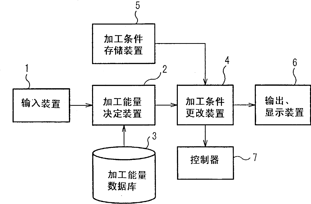
[0033] Fig. 1 is a structural diagram showing Embodiment 1 of the present invention. In the figure, 1 is an input device, usually a keyboard. 2 is a processing energy determining device, and 3 is a processing energy database. In this database, as shown in FIG. Described above in proportion to standard processing conditions. Here, the nozzle height indicates, for example, a state where the nozzle 70 is separated from the workpiece 72 as shown in FIG. 10A . This ratio data only refers to the first processing. The processing energy determination device 2 determines the processing energy according to the plate thickness read from the processing energy database 3, the relevant data of the height of the upper nozzle and the height of the lower nozzle. In the processing energy determining device 2 , the determined processing energy data is sent to the processing condition changing device 4 . 5 is a processing condition storage device, which stores charging voltage, conduction tim...

Embodiment 2

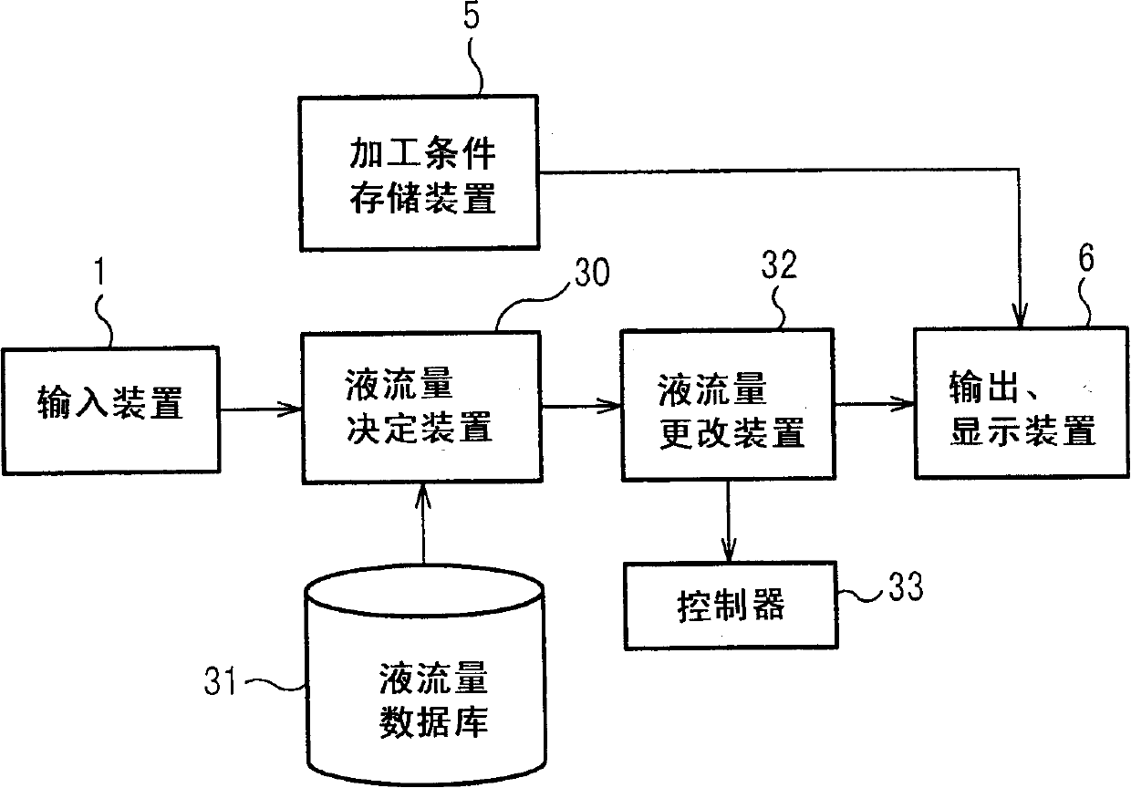
[0043] Fig. 4 is a configuration diagram showing Embodiment 2 of the present invention, and Fig. 5 is a flow chart showing the operation of Embodiment 2 of the present invention. Among the figure, 1 is the input device identical with embodiment 1, adopts keyboard usually. 30 is a liquid flow determining device related to the machining fluid flow (hereinafter referred to as liquid flow), and 31 is a liquid flow database. In this liquid flow database 31, as shown in FIG. Corresponding to the height of the nozzle, the liquid flow rate under the continuous line condition is described in proportion to the usual above-mentioned standard processing conditions. The data for this ratio only refer to the first processing. The liquid flow determining means 30 determines the liquid flow based on the data read from the liquid flow database 31 . The liquid flow data determined by the liquid flow determining device 30 is sent to the liquid flow changing device 32 . 5 is the same processin...

Embodiment 3

[0049] Fig. 7 is a configuration diagram showing the third embodiment of the present invention, and Fig. 9 is a flow chart showing the operation of the third embodiment of the present invention. Among the figure, 1 is an input device, and like embodiment 1, adopts keyboard usually. 50 is an inclination correction value determining device, and 51 is an inclination correction value database. As shown in FIG. The correction value of the line inclination of the whole process in the standard processing is described. In the inclination correction value determining means 50 , the line inclination correction value is determined based on the data read from the inclination correction value database 51 . The inclination correction value data determined by the inclination correction value determining device 50 is sent to the multi-process inclination correction value changing device 52 . 53 is a multi-process processing condition storage device, which stores charging voltage, conduction...


PUM


Abstract

A wire electric discharge machining device capable of machining a work under specified working conditions by using working fluid provided in a clearance between a wire and the work, comprising a machining condition storage means for holding machining conditions, a means for storing the relation between a nozzle height and a machining energy amount, a machining energy determination means for determining, for example, the machining energy amount in a rough machining based on the relation, and a machining condition alteration means for altering the machining conditions according to the machining energy amount, wherein the work is machined under the altered machining conditions, whereby a damage to the wire can be prevented and the accuracy of a machined surface can be increased.

Description

technical field [0001] The present invention relates to a wire electric discharge machining device. Background technique [0002] Generally, wire electric discharge machining is divided into rough machining, intermediate machining, intermediate finishing machining, and finishing machining, and machining is performed in three to seven steps while sequentially switching machining conditions from high energy to low energy. Its purpose is to shorten the processing time by gradually improving the smoothness of the processed surface, and to improve the straightness of the processed surface. Furthermore, as we all know, in wire electric discharge machining, the machining produces discharge repulsion, electrostatic force, etc., which cause the wire to vibrate, so that the wire part facing the center of the workpiece is depressed or swells, that is, it becomes "bulging". shape". In addition, in the wire electric discharge machining, the machining state is completely different in th...

Claims


Application Information

Patent Timeline
Patent Type & Authority Applications(China)
IPC IPC(8): B23H7/20
CPCB23H7/20
Inventor 千代知子榎本耕二安田治河合泰弘佐藤清侍
Owner MITSUBISHI ELECTRIC CORP
Why Eureka
Try Eureka