Supercharge Your Innovation With Domain-Expert AI Agents!

Grain growth of electrical interconnection for microelectromechanical systems (MEMS)

A technology of micro-electromechanical systems and grain growth, applied in piezoelectric devices/electrostrictive devices, fluid pressure measurement using capacitance changes, piezoelectric/electrostrictive/magnetostrictive devices, etc., can solve welding defects, Leakage and other issues

Inactive Publication Date: 2003-01-29
ROSEMOUNT INC
View PDF0 Cites 2 Cited by
  • Summary
  • Abstract
  • Description
  • Claims
  • Application Information

AI Technical Summary

Problems solved by technology

Therefore may cause welding defects or leaks

Method used


Image

  • Grain growth of electrical interconnection for microelectromechanical systems (MEMS)
  • Grain growth of electrical interconnection for microelectromechanical systems (MEMS)
  • Grain growth of electrical interconnection for microelectromechanical systems (MEMS)

Examples


Embodiment Construction

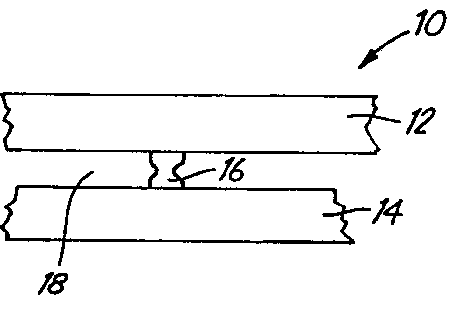
[0028] figure 1 is a simplified cross-sectional view of a portion of MEMS device 10 of the present invention. MEMS device 10 includes upper layer 12 and lower layer 14 . The layers 12 and 14 are electrically coupled together by the electrical connection 16 of the present invention. As explained in detail herein, electrical connection 16 is formed by a grain growth process to electrically couple said layers 12 and 14 together. Generally speaking, the invention can be used to provide a connection between two planar substrates, said connection extending in a vertical direction (ie the third dimension of the substrate). For example, electrical connection 16 may bridge gap 18 between two layers 12 and 14 . This technology can be used in various types of MEMS devices, such as pressure, acceleration, flow sensors, etc. Much of this specification that follows is specifically concerned with the use of, for example, figure 1 Connection 16 is shown for the pressure sensor. However,...


PUM


Abstract

An isolated connection is formed by growing interconnects from the grain growth of an electrically conductive grain growth material (16) inside an MEMS device (10) after the device (10) is bonded together. The material used for grain growth of electrical contacts is deposited inside a cavity (18) formed between first (12) and second layers (12) of the device (10).

Description

technical field [0001] The present invention relates to microelectromechanical systems. In particular, the present invention relates to electrical connections in such systems. Micro-Electro-Mechanical Systems (MEMS) are small devices that provide certain electrical and mechanical properties and are generally manufactured in batches. MEMS are widely used in many electronic devices. Examples of MEMS include acceleration, pressure, flow, displacement, distance, sensors and actuators for valves, pumps, and optics. One particular use of MEMS sensors is for pressure sensing. Background technique [0002] In aerospace or industrial fluid sensor applications, the sensing element, metal film and connections used in the sensor manufacturing process are subject to corrosion by the fluid (medium). Corrosive fluids may include gases, acids, bases, oils, petrochemicals, food, etc. in aerospace or stationary turbine engines. [0003] The sensing element is preferably placed between th...

Claims


Application Information

Patent Timeline
IPC IPC(8): G01L9/12B81B3/00B81B7/00B81C99/00G01L9/00H01L29/84
CPCG01L9/0075B81B7/0006
Inventor 马克·G·罗莫小斯坦利·E·鲁德马克·A·卢茨弗雷德·C·西特勒阿德里安·C·托伊
Owner ROSEMOUNT INC
Features
  • R&D
  • Intellectual Property
  • Life Sciences
  • Materials
  • Tech Scout
  • Unparalleled Data Quality
  • Higher Quality Content
  • 60% Fewer Hallucinations
Learn More