Turbine blade arrangement

A technology for turbine blades and blades, applied in the direction of supporting elements of blades, machines/engines, leakage prevention, etc., to achieve the effect of firm clamping, simple connection, and good force distribution

Inactive Publication Date: 2003-02-19
SIEMENS AG
View PDF0 Cites 22 Cited by
  • Summary
  • Abstract
  • Description
  • Claims
  • Application Information

AI Technical Summary

Problems solved by technology

However, at this stage, this load has almost reached its maximum value and it i

Method used


Image

  • Turbine blade arrangement
  • Turbine blade arrangement
  • Turbine blade arrangement

Examples


Embodiment Construction

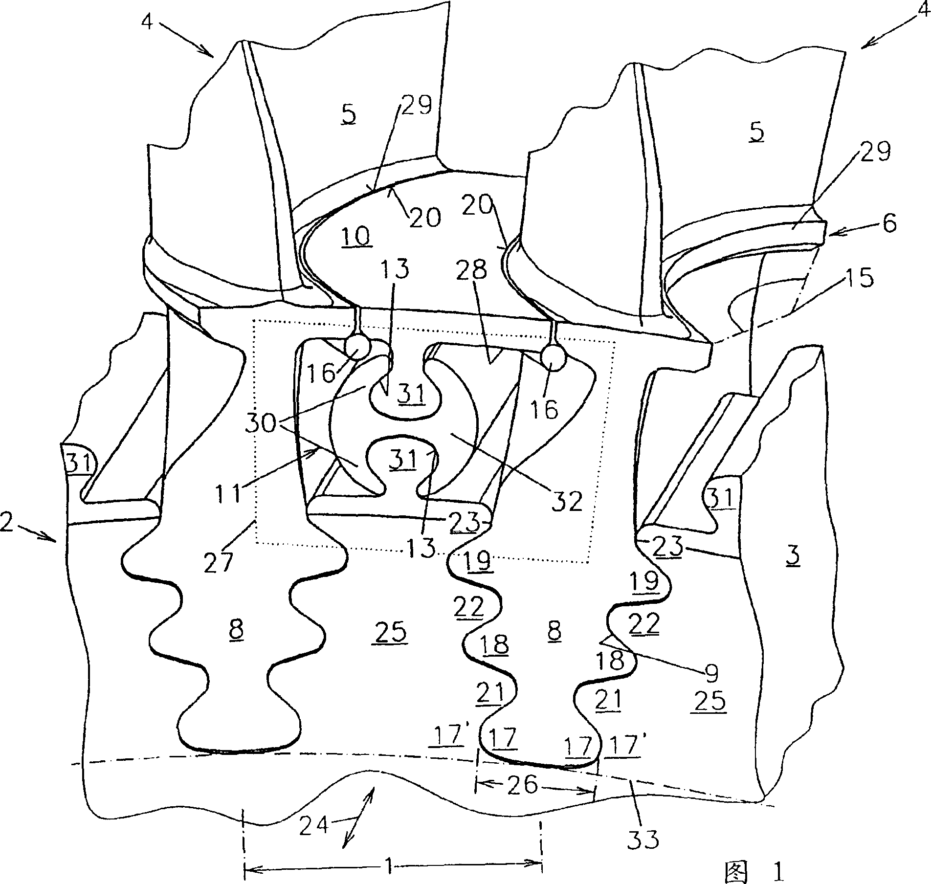
[0020] Figure 1 shows a perspective view of a turbine blade arrangement. The turbine disk 3 with the rotating blades 4 is driven in rotation about the turbine shaft 24 by means of a hot working fluid, especially hot gas in a gas turbine, passing through the turbine and onto the airfoil 5 . The rotating blades 4 are inserted with their pine-like roots 8 into the grooves 9 with the spacing 1 on the outer circumference 2 of the turbine disk 3 by lateral pushing. As a result of the rotational movement of the turbine disk 3 , the rotating blades 4 are acted upon by centrifugal forces directed towards the outside. This centrifugal force is absorbed by the roots 8 of the rotating blades 4 and the claws 25 of the turbine disk 3 by means of various teeth 17, 18, 19, 21, 22, 23 formed on the roots 8 in a pine tree-like manner and resting on the claws. 25 have integrally formed parts corresponding to them. The bottom root teeth 17 on both sides of the root 8, the middle root teeth 18 a...


PUM


Abstract

The invention relates to a turbine blade arrangement consisting of rotating blades (4) respectively provided with a leg (8) which can be respectively inserted into a groove (9) on the outer circumference (2) of a turbine disk in a radial, positive fit and which are respectively provided with a profiled section (5) which has a lateral platform (6) located in an end area on the side of the disk. According to the invention, at least one part (10) of the platform is joined to the turbine disk by means of a retaining element which is independent from the leg (8) of the blades in order to extend the profiled sections of the rotating blades.

Description

technical field [0001] The invention relates to a turbine blade arrangement with rotating blades, which are arranged at predetermined intervals on the outer circumference of a turbine disk and each have a blade root which can in each case be form-locked Inserted radially into grooves on the periphery of the turbine disk, and the blades each have a profile having a platform transversely at the turbine disk-side end region. Background technique [0002] In order to increase the efficiency or turbine power output, and thus the effective cross-section of the turbine, the profile of the turbine rotating blades is usually lengthened in order to achieve better utilization of the passing hot working fluid or greater power output. However, this elongation of the airfoil is limited by various parameters. [0003] In particular, the elongated airfoil and the correspondingly increased moving mass exert a large load in the hub region of the turbine disk due to the centrifugal forces act...

Claims


Application Information

Patent Timeline
IPC IPC(8): F01D5/30F01D11/00
CPCF01D5/3007F01D11/008
Inventor 彼得·蒂曼迈克尔·斯特拉斯伯格
Owner SIEMENS AG
Why Eureka
Try Eureka