Flowing mechanical treater for page-type printing material

A technology of printing materials and flowing machinery, applied in general parts of printing machinery, printing presses, thin material processing, etc., to achieve the effect of simple cost

Inactive Publication Date: 2003-03-05
HEIDELBERGER DRUCKMASHINEN AG
View PDF6 Cites 7 Cited by
  • Summary
  • Abstract
  • Description
  • Claims
  • Application Information

AI Technical Summary

Problems solved by technology

The disadvantage of similar devices in the prior art is that only one processing met

Method used


Image

  • Flowing mechanical treater for page-type printing material
  • Flowing mechanical treater for page-type printing material
  • Flowing mechanical treater for page-type printing material

Examples


Embodiment Construction

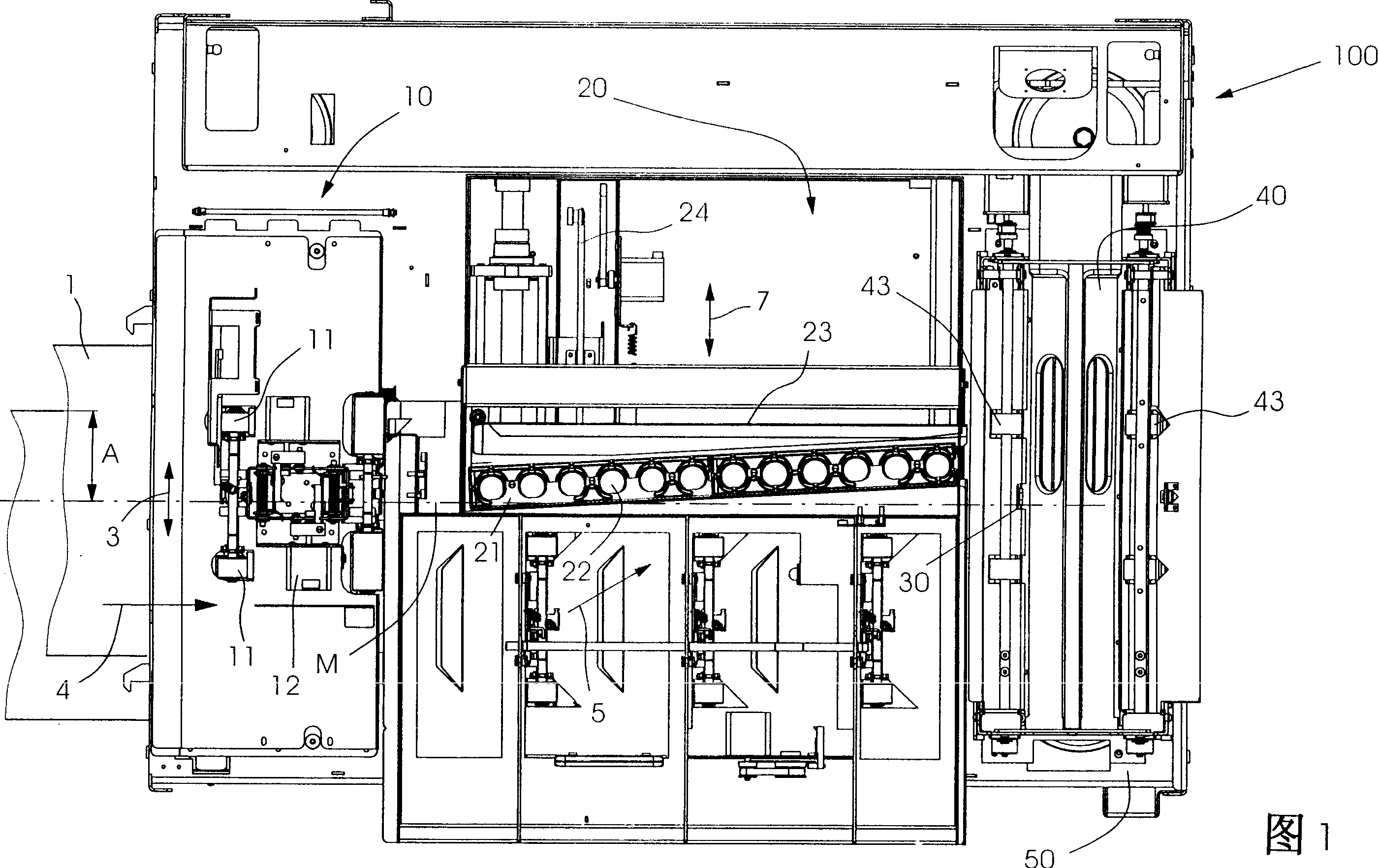
[0053] FIG. 1 shows a schematic plan view of the overall structure of a preferred embodiment of a device 100 according to the invention, and the description here is limited to the components according to the invention. Furthermore, generally known drives and / or guides and cams and electrical circuits for operating the device are only shown schematically or described in general form.

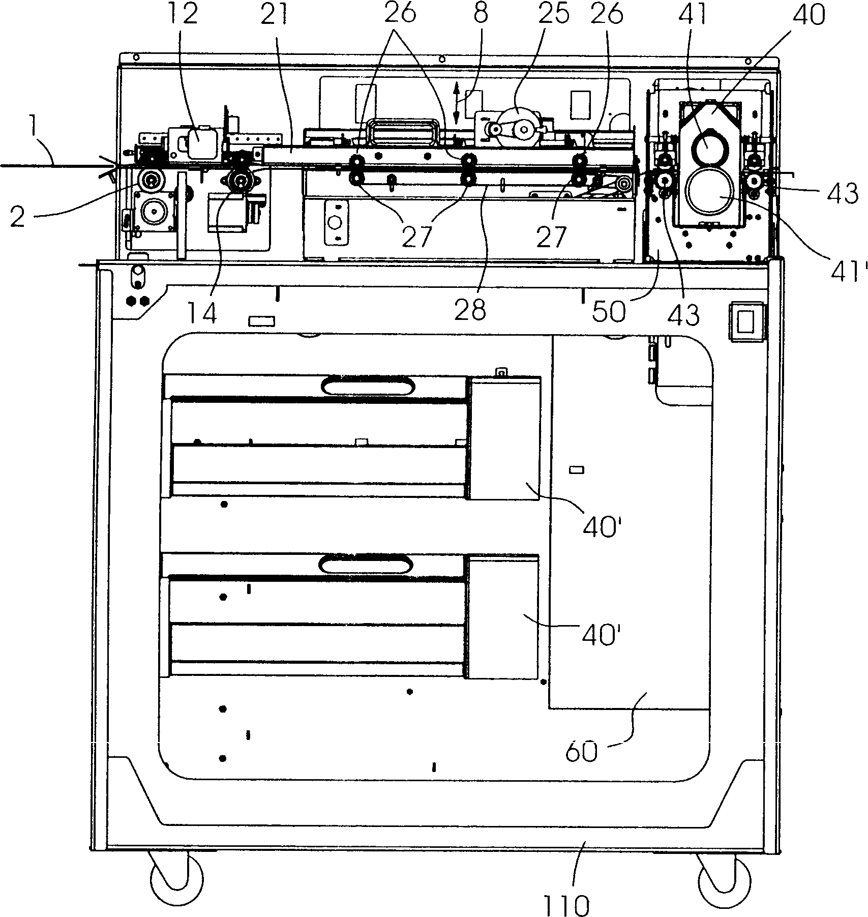
[0054] Figure 1 and figure 2 As shown in , the sheet-like printing material enters the device according to the invention in the vicinity of a transport roller pair 2, and wherein the side edge of the sheet-like printing material 1 passes through the sheet-like printing material 1 along the direction of movement indicated by the reference number 4 according to The centerline M of the transport path of the device 100 of the present invention has a distance A. As shown in FIG. In a prepositioning device 10 the distance A is determined by means of an edge sensor (not shown) and transmitted to a logi...


PUM


Abstract

To improve a device for on-the-fly machine-working a sheet-like print material (1) to allow a large number of working modes, and to make change among the respective working modes executed quickly, simply and inexpensively. A working tool (45) comprising two portions is arranged in one of working modules (40, 40'), the device (100) has a storage space (50), the working modules (40, 40') are fixed to allow replacement in the storage space (50), and the space 50 stores also at least the one of the working module (40, 40') having at least the one another working module.

Description

technical field [0001] The invention relates to a device for the flow-mechanical treatment of sheet-like printing material according to the preamble of claim 1 . Background technique [0002] In the printing industry there is a need for mechanical processing of printed material, especially in preparation for post-print processing for the binding process by which individual printed sheets are assembled into volumes, books or the like . [0003] Flow processing of printed materials is one of the many post-processing possibilities available for example from H. Kipphan, "Handbook of Printed Media", Springer Verlag (2000). "Flow processing" is understood here to mean that the sheet-like printing material is processed in motion, as opposed to a system in which a plurality of sheet-like printing material is perforated or edge-cut, for example, in a stationary state. As a rule, in flow processing the printed sheets are processed individually and then collected, whereas in other me...

Claims


Application Information

Patent Timeline
IPC IPC(8): B41F13/56B23D35/00B26F1/00B26F1/04B26F1/10B26F1/38B31F1/07B41F19/02B41F19/08B41F33/14B42C5/00B65H37/00
CPCB31F2201/0776B31F2201/0738B23D35/008B31F2201/0779B31F1/07B26F1/384B26F1/10B26F1/04
Inventor 库尔特・布兰克爱德华・米勒于尔根・里斯
Owner HEIDELBERGER DRUCKMASHINEN AG
Why Eureka
Try Eureka