

Leakage breaker
A leakage circuit breaker and main circuit technology, which is applied in the direction of switches operated by ground fault current, switches with multiple unbalanced current/voltage effects, etc., can solve the difficulty of adjusting the test spring 12 and the plate spring, and increase the size of the leakage circuit breaker , complex structure and other issues
- Summary
- Abstract
- Description
- Claims
- Application Information
AI Technical Summary
Problems solved by technology
Method used
Image

Examples
Embodiment Construction
[0043] Embodiment 1
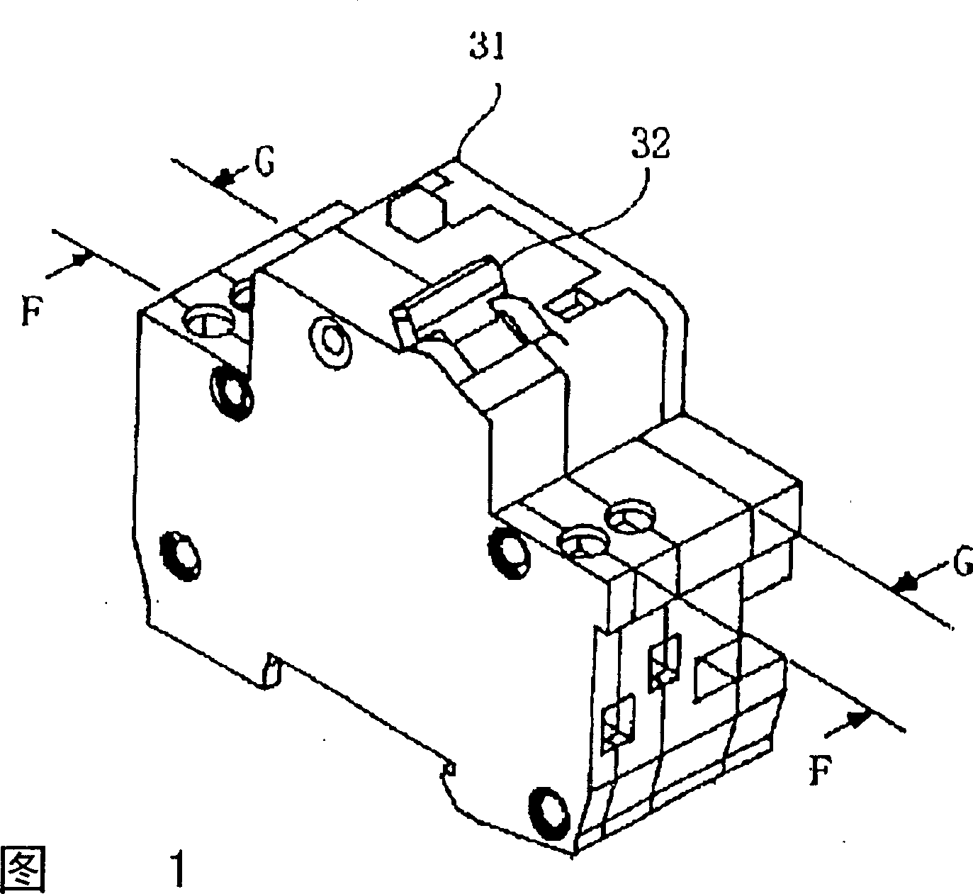
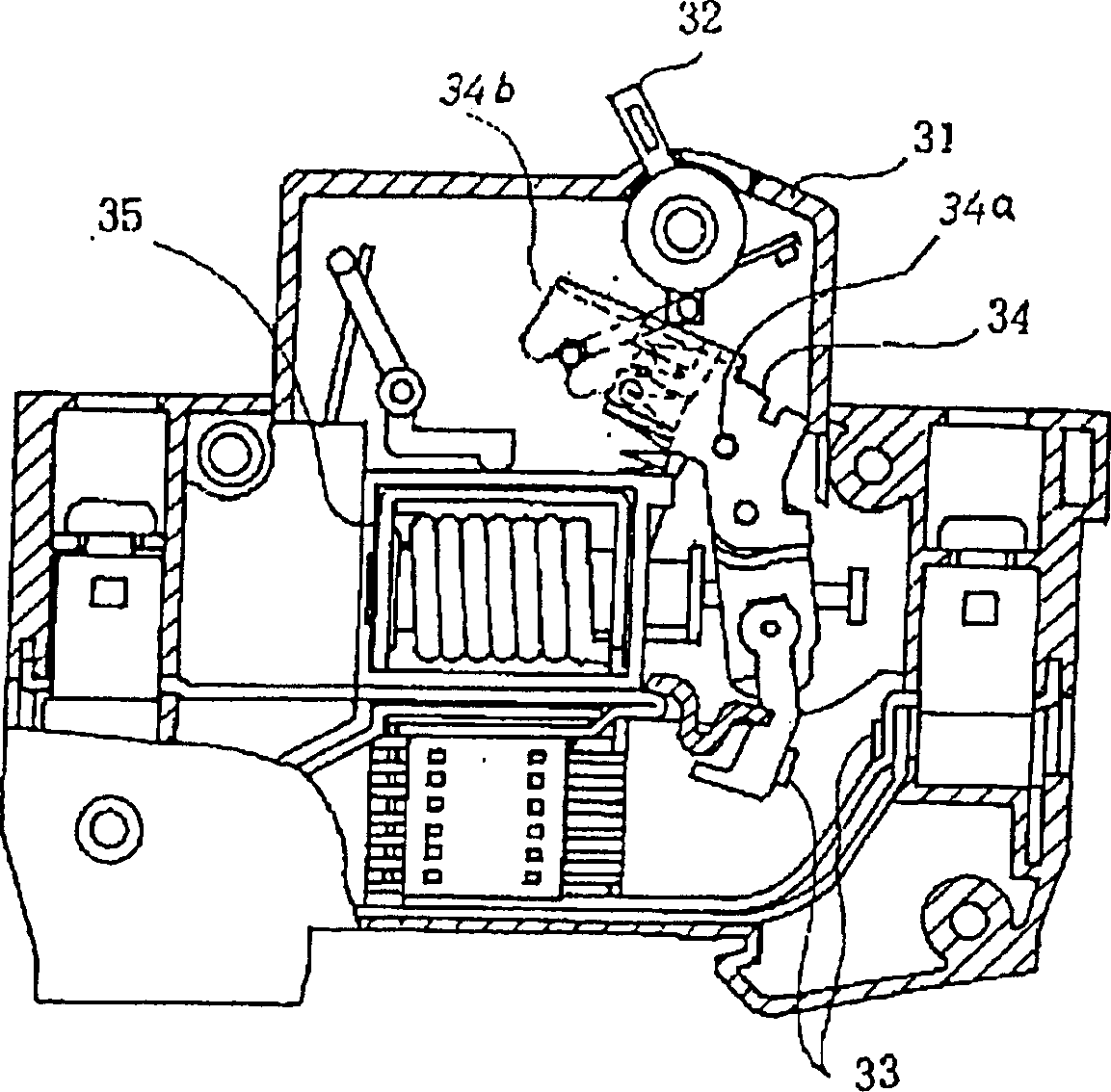
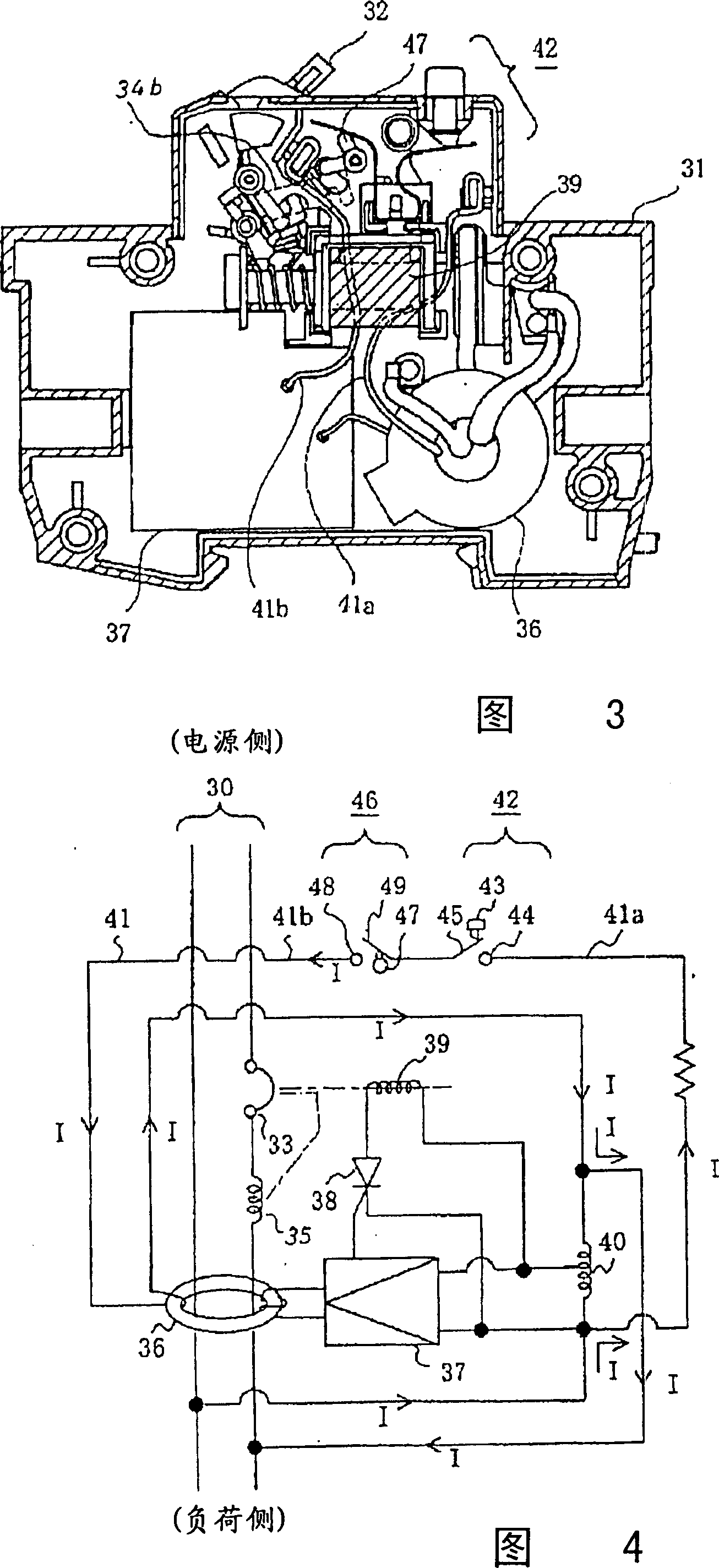
[0044] Fig. 1 shows the perspective view of the appearance of an earth leakage circuit breaker according to Embodiment 1 of the present invention, figure 2 Shown is a longitudinal sectional view along the F-F line when the leakage circuit breaker in Fig. 1 is in an open state, and Fig. 3 is a longitudinal sectional view along the G-G line when the leakage circuit breaker in Fig. 1 is in an off state, and Fig. 4 shows The circuit diagram of the connection state between the leakage circuit breaker and the main circuit in Fig. 1, Figure 5 Shown is an enlarged longitudinal sectional view of the main parts of the leakage circuit breaker in Figure 1 when it is disconnected or tripped. Figure 6 Shown is the enlarged longitudinal sectional view of the main part of the leakage circuit breaker in Fig. 1 when it is closed. Figure 7 shown as Figure 5 The enlarged perspective view of the plate-shaped elastic member of , Figure 8 shown as Figure 5 An enlarg...
PUM
 Abstract
Description
Claims
Application Information