

Method for dynamic control of nondestructive replacement of tied arch bridge hanger rod
A technology of dynamic control and tie-rod arch bridges, applied in arch bridges, bridges, bridge maintenance, etc., can solve problems such as bridge deck damage, and achieve the effect of less engineering
- Summary
- Abstract
- Description
- Claims
- Application Information
AI Technical Summary
Problems solved by technology
Method used
Image

Examples
Embodiment
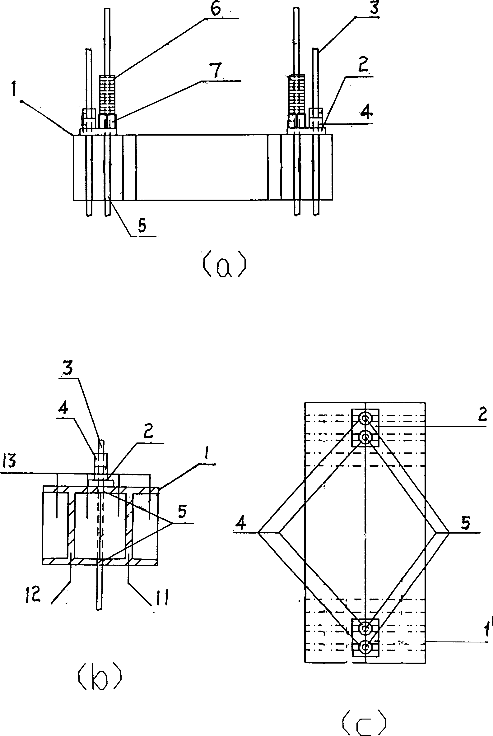
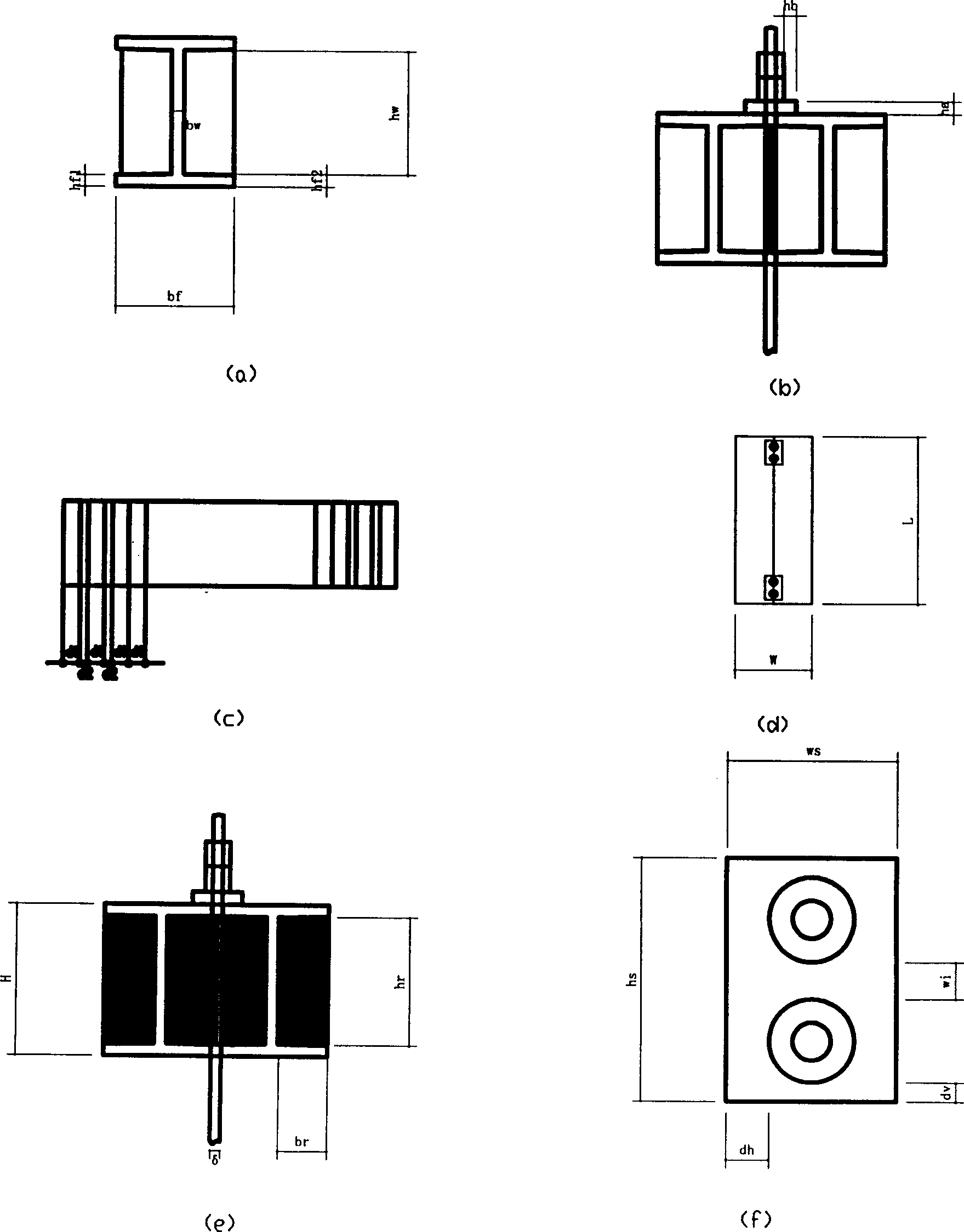
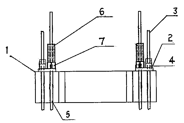
[0031] Embodiment, the following takes the replacement of the suspender of a mid-supporting suspender arch bridge as an example to specifically illustrate the structure of the device, and the values of the control parameters of the device are as follows:
[0032] (a) Flange width b of welded I-beam f = 120mm, flange thickness h f1 = 12mm, h f2 =20mm, web height h w =310mm, web width b w =20mm;
[0033] (b) Outline dimensions of the tool suspender after tailor welding: length L, width W=280mm, height H=350mm.
[0034] (c) Dimension h of local pressure backing plate s ×ws =280×1650mm 2 .
[0035] (d) Parameters of stiffening steel ribs: number n=6, rib thickness ω=20mm, d 1 = d 2 =80mm, the total length of the rib is l=440mm.
[0036] (e) The size control parameters of the finish-rolled rebar are its diameter δ=32mm, and its length is 2.5m, 4.5m, 9m and so on.
[0037] (f) CY70 jack is selected for the hydraulic jack.
[0038] (h) The size of each load is m=120kN, ...
PUM
 Abstract
Description
Claims
Application Information