
Damping intermediate column and damping structure using same

A damping structure and intermediate column technology, applied in truss structures, building components, building structures, etc., can solve the problems of insufficient joint strength and easy fracture, and achieve improved strength, easy resistance, and increased shear deformation. Effect

Inactive Publication Date: 2003-03-12
笠井和彦 +1
View PDF0 Cites 9 Cited by
  • Summary
  • Abstract
  • Description
  • Claims
  • Application Information

AI Technical Summary

Problems solved by technology

However, since the upper and lower end portions of the resistance intermediate column 4 are simply fixedly connected to the beams 3a, 3b of the upper and lower floors by bolts or welding, the joint strength is insufficient to resist an earthquake of a large magnitude.
As a result, the junction 9a between the damping intermediate column 4 and the beam 3 is unduly prone to breakage before performing the damping function.

Method used


Image

  • Damping intermediate column and damping structure using same
  • Damping intermediate column and damping structure using same
  • Damping intermediate column and damping structure using same

Examples


Embodiment Construction

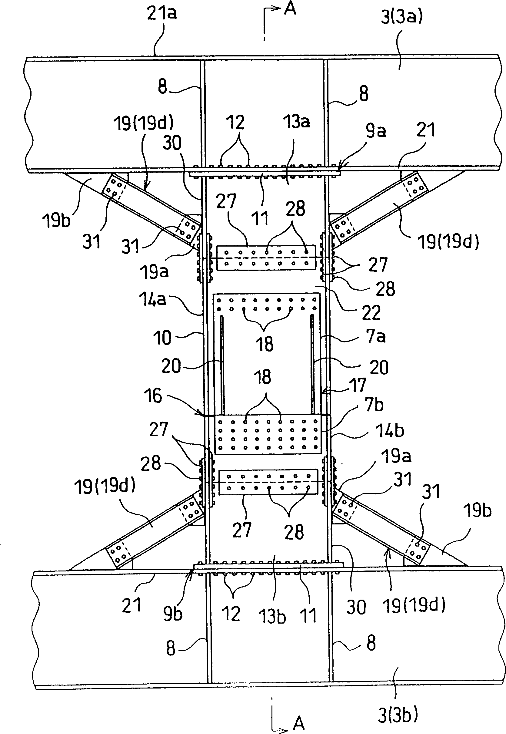
[0049] Some embodiments of the present invention will be described in detail below with reference to the accompanying drawings.

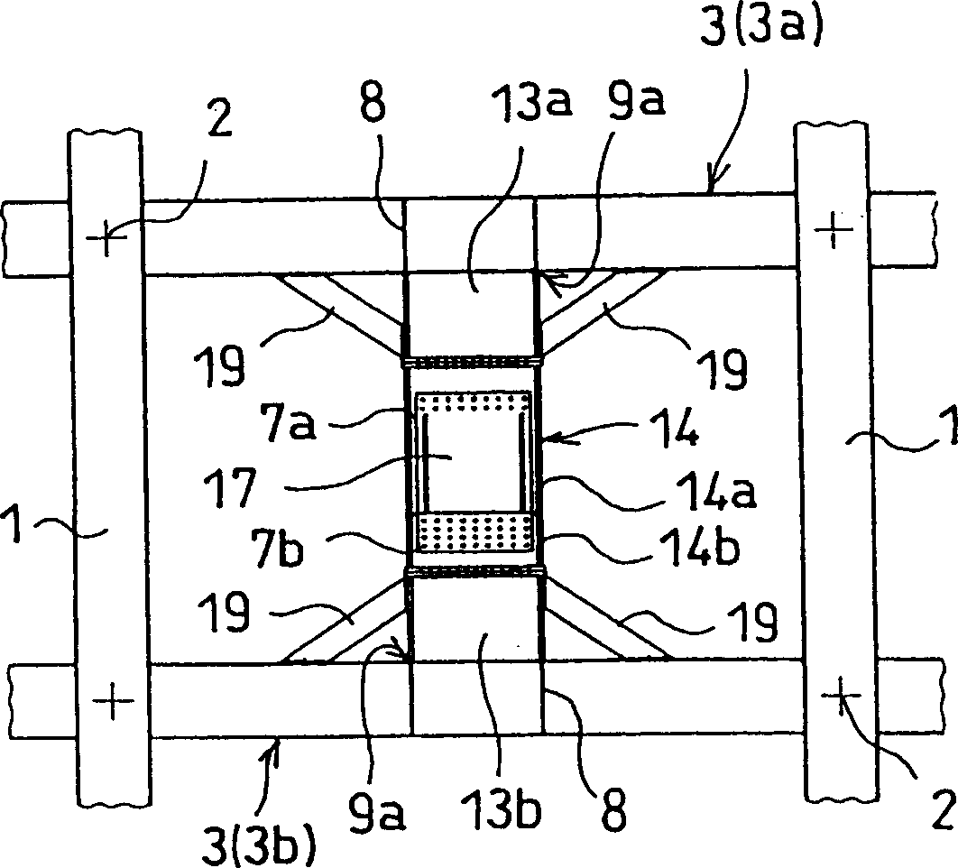
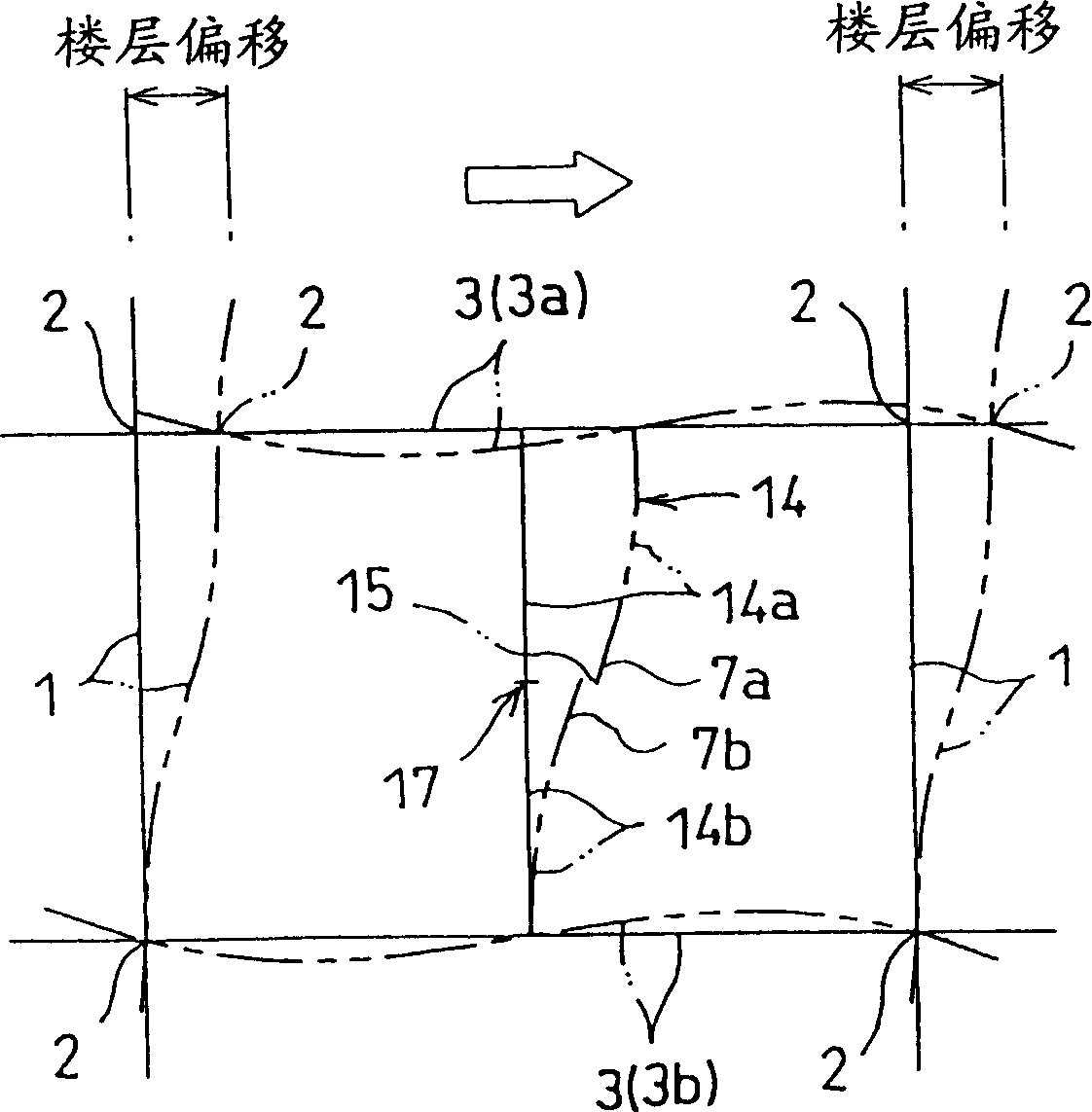
[0050] 1-4 show a first embodiment of the invention, where Figure 1A and 1B Corresponds to the prior art used to illustrate the Figure 23A and 23B , are schematic diagrams showing the structural configuration of the damping intermediate column in which the viscoelastic damper is incorporated, and these figures are used to illustrate the damping effect of the building frame.

[0051] In FIG. 1 , the framework of the building includes a rectangular steel pipe pillar 1 filled with concrete and a wide-rim I-shaped steel beam 3 , which are connected to each other by a pillar-beam joint 2 . The structure also comprises a damped intermediate column 14 with a viscoelastic damper 17 placed between the beams 3a and 3b of the upper and lower floors. The structure for fixing the damping intermediate column 14 and the beam 3 is different from that of the pr...


PUM


Abstract

A damping intermediate pillar, which can exhibit a sufficient resistance against the horizontal force of a strong earthquake by reinforcing the joins between the damping intermediate pillar and the upper and lower beams, is disclosed. A damping intermediate pillar 14, used for a building or a structure configured of pillars 1 and beams 3, is divided into upper and lower damping intermediate pillar portions 14a, 14b of H shape steel, and includes a plurality of inner steel plates 7b fixed on the damping intermediate pillar portion 14b and a plurality of outer steel plates 7a fixed on the other damping intermediate pillar portion 14a. The inner and outer steel plates are arranged alternately in a single or a plurality of layers, between which a viscoelastic member 15 is held to make up a viscoelastic damper 17. The coupling end surfaces of the intermediate pillar portions 14a, 14b directed vertically are fixed on the upper and lower floor beams 3a, 3b. Further, one or both sides of each of the damping intermediate pillar portions 14a, 14b (i.e. the coupling members 13a, 13b) and the upper and lower floor beams 3a, 3b are coupled to each other by knee braces 19.

Description

technical field [0001] The present invention relates to a damping (vibration damping) intermediate column and a damping structure using such a damping column, which is used to absorb input vibration energy, or in particular, to absorb the frame structure of a building and various Horizontal forces in other structures. Background technique [0002] Commonly used techniques in this category include the following (1)-(7): [0003] (1) Japanese Unexamined Patent Publication No. 2000-274108 concerning a viscoelastic damper structure directly coupled to upper and lower floor beams, (2) Japanese Unexamined Patent Publication No. 2000-54680 , relating to a detailed structure for mounting viscoelastic dampers on upper and lower floor beams, (3) Japanese Unexamined Patent Publication No. 2000-73605, relating to a laminated steel plate for viscoelastic dampers , (4) Japanese Unexamined Patent Publication No. 2000-73608, relating to a technique for coupling a viscoelastic damper, (5) ...

Claims


Application Information

Patent Timeline
Patent Type & Authority Applications(China)
IPC IPC(8): E04B1/24E04H9/02F16F15/04
CPCE04B2001/2442E04B2001/2445E04B2001/2448E04H9/02E04B2001/2415E04H9/0237
Inventor 笠井和彦中村博志中田安洋白井贵志
Owner 笠井和彦
Learn More