
Printing method of hot printing head

A thermal printing head and printer technology, applied in the field of grayscale printing, can solve the problems of wasting time and increasing production costs, and achieve the effects of improving color resolution, saving time and improving effects

Inactive Publication Date: 2003-03-19
HI TOUCH IMAGING TECH CO LTD
View PDF0 Cites 17 Cited by
  • Summary
  • Abstract
  • Description
  • Claims
  • Application Information

AI Technical Summary

Problems solved by technology

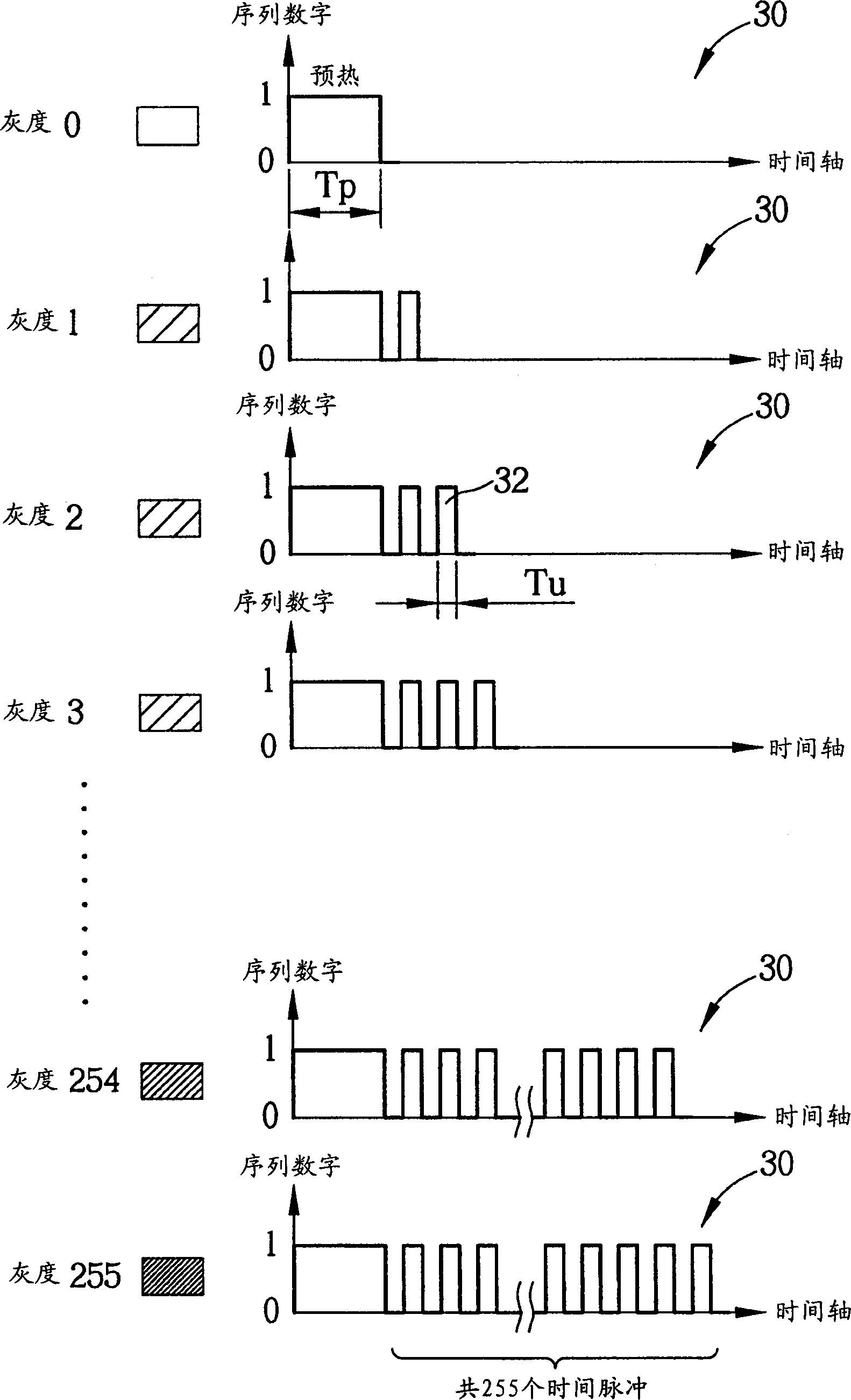
If want to increase the number of color gray scales to twice the original number, multiple heaters 22 must complete the time length of 512 time pulses, therefore, if you want to increase the number of color gray scales to the original several times, you need to complete more time pulses, such that increasing color resolution in this way wastes a lot of time and increases production costs

Method used


Image

  • Printing method of hot printing head
  • Printing method of hot printing head
  • Printing method of hot printing head

Examples


Embodiment Construction

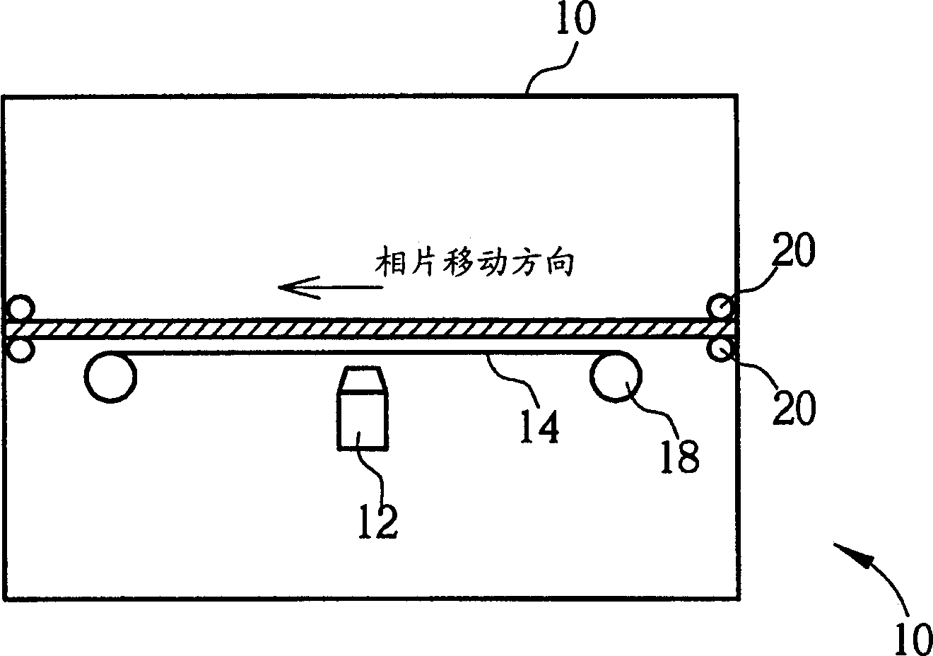
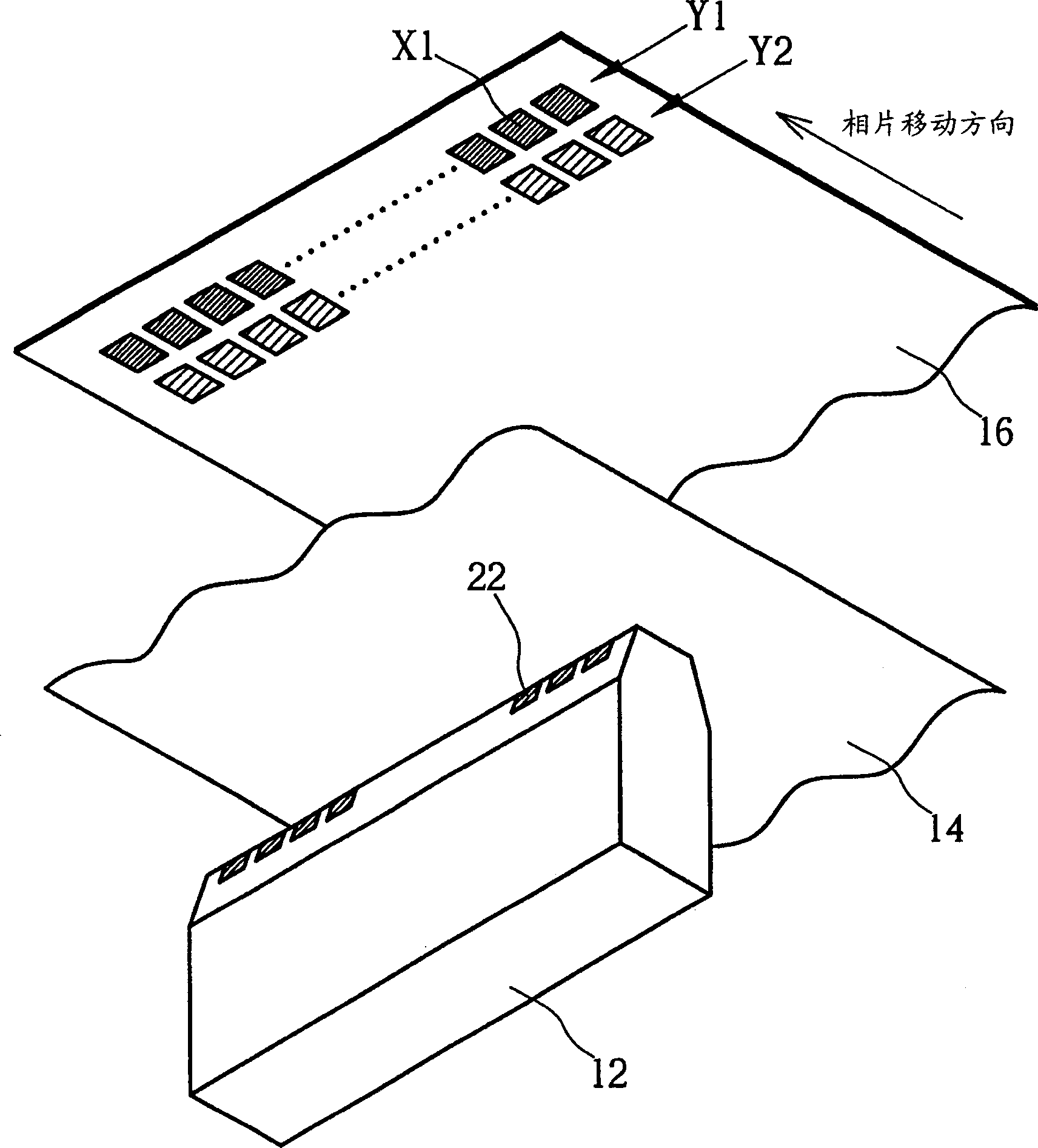
[0018] The photo printer of the present invention and the structure of thermal printing head and printing feeding mode and figure 1 and figure 2 The prior art shown is the same, so the description will not be repeated. As previously described, before the thermal print head of the photo printer of the present invention prints a photo paper, a plurality of heaters on the thermal print head can be turned on simultaneously (the digital signal value of turning on the heater is "1", and the heater is turned off. digital signal value of "0") a predetermined time Tp so that all the heaters of the thermal print head reach a predetermined temperature, which is the preheating stage, and then, according to the number of multiple line images on the photo paper The number of gray scales required for a corresponding print dot X2 is used to continuously turn on multiple heaters on the thermal print head.

[0019]Since the length of heating time of each heater can be represented by a time p...


PUM


Abstract

The present invention provides one kind of method to increase the printed color density and grey of the hot printing head. The hot printing head includes several heaters arranged linearly in the equal interval to heat the color ribbon, so that the color dye on the color ribbon can form one linear pattern on the photographic paper and the number of the heaters is the number of the printed points in the linear pattern. The color density and grey of each printed point depends on the time for the corresponding heater to heat the color ribbon and the time is determined by one time pulse sequence, which includes one integral number part and one tail number part corresponding to the grey.

Description

technical field [0001] The invention relates to a printing method of a thermal printing head, in particular to a printing method for increasing the grayscale number of the thermal printing head. Background technique [0002] The main difference between photo printers and general printers is that photo printers can print higher-quality images, such as high-quality photos. Please refer to figure 1 as well as figure 2 , figure 1 It is a schematic diagram of an existing photo printer 10; figure 2 It is a schematic diagram of the printing feeding mode of the conventional photo printer 10 . Such as figure 1 As shown, the existing photo printer 10 includes a color ribbon 14 on which a plurality of dye blocks are used to store colored dyes of different colors, and a thermal print head 12 is fixed on the photo printer 10 for printing a dye Heating has made this colored dye print on a photo paper 16, and a ribbon moving device 18 is used to move the ri...

Claims


Application Information

Patent Timeline
Patent Type & Authority Applications(China)
IPC IPC(8): B41J2/36
Inventor 方御凡黄光辉
Owner HI TOUCH IMAGING TECH CO LTD
Learn More