Thin film thermosensitive resistor and tis resistance valve regulating method

A thin-film thermistor and heat-sensitive technology, applied in the thermistor, resistor, resistor manufacturing and other directions, can solve the problems of reduced contact strength, difficulty in producing small-tolerance products, and unstable electrical characteristics of thermal films. , to prevent component changes, improve reliability, and achieve the effect of small deviations

Inactive Publication Date: 2003-04-09
ISHIZUKI ELECTRONICS
View PDF3 Cites 24 Cited by
  • Summary
  • Abstract
  • Description
  • Claims
  • Application Information

AI Technical Summary

Problems solved by technology

In this way, it is difficult to produce products with tight tolerances cut by laser
In addition, the decrease in the contact strength between the heat-sensitive film and the insulating substrate destabilizes the electrical characteristics of the heat-sensitive film

Method used


Image

  • Thin film thermosensitive resistor and tis resistance valve regulating method
  • Thin film thermosensitive resistor and tis resistance valve regulating method
  • Thin film thermosensitive resistor and tis resistance valve regulating method

Examples


Embodiment Construction

[0064] Explanations will now be given of various embodiments of the thin film thermistor according to the present invention with reference to the drawings.

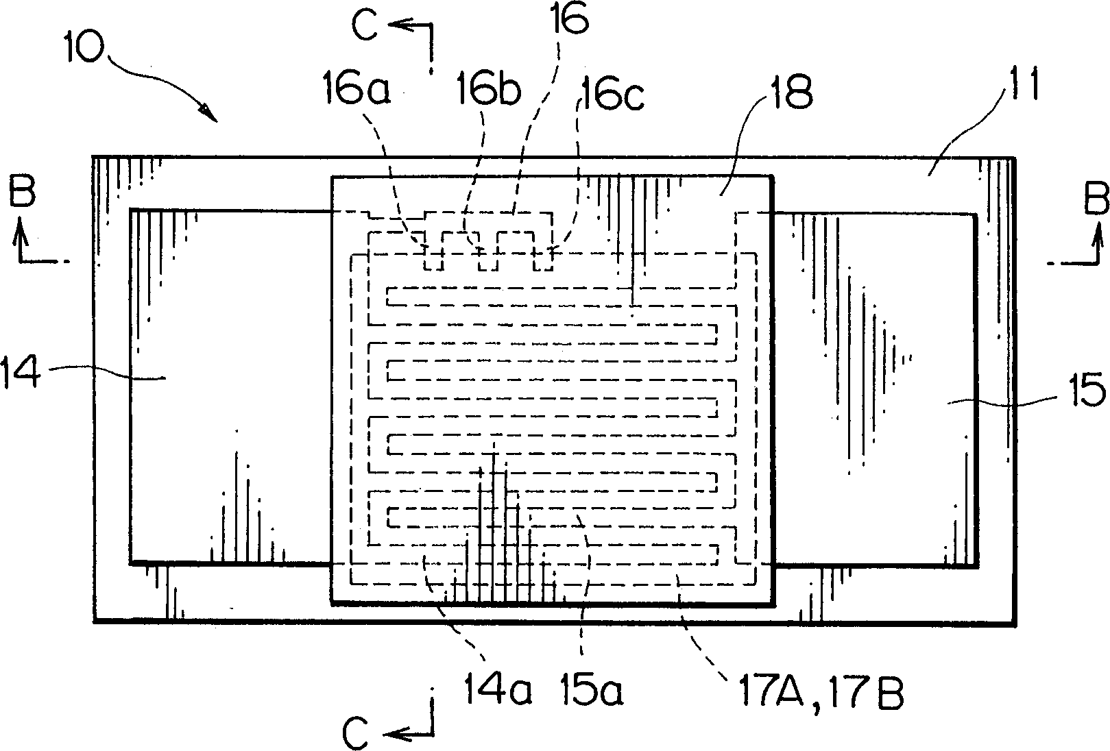
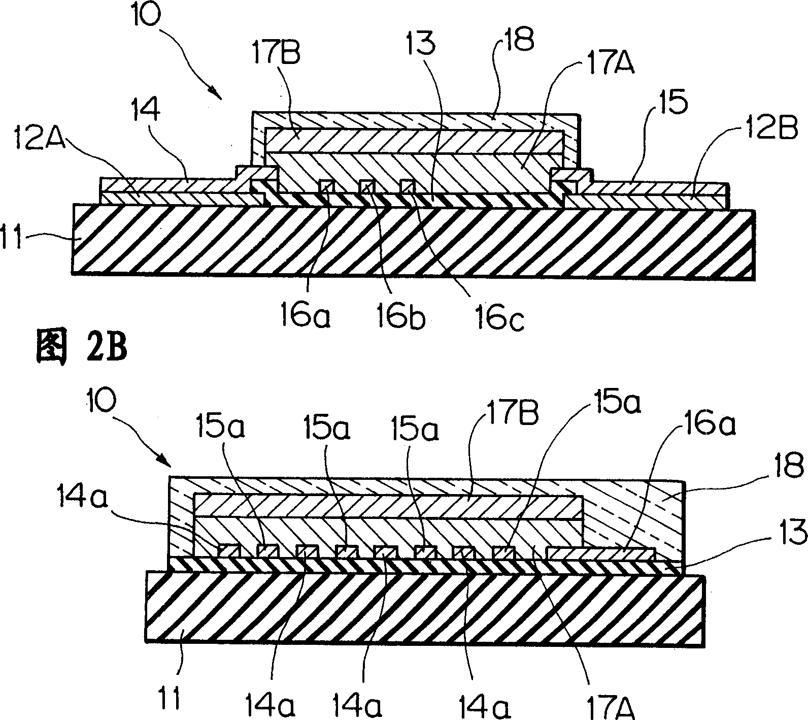
[0065] exist figure 1 and 2, reference numeral 10 denotes a thin film thermistor. The thin film thermistor 10 includes: an insulating substrate 11; a pair of opposite lower electrodes 12A and 12B formed on the insulating substrate 11; an insulating coating 13 formed between the lower electrodes 12A and 12B; lead electrodes 14 and 15 ; The comb electrodes 14a and 15a extending from the extraction electrodes 14 and 15 to the insulating coating 13; the metallic pattern 16 for resistance adjustment electrically connected with the extraction electrodes 14, which has a cutting portion 16a for cutting , 16b and 16c; a first thermosensitive film 17A formed over the comb electrodes 14a and 15a; a second thermosensitive film 17B formed over the first thermosensitive film 17A; and a protective film 18.

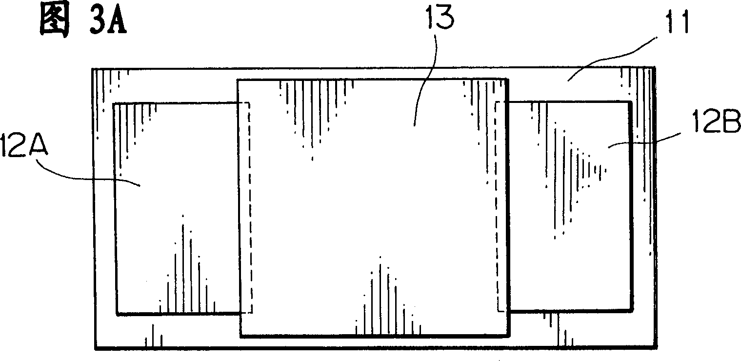
[0066] Referring to FIG. 3...


PUM


Abstract

In a thin film thermistor with a cutting portion of a metallic pattern for resistance adjustment, initially, the resistance is roughly adjusted by adjusting the film thickness of a second heat-sensitive film, and secondly finely adjusted by trimming the cutting portion by laser irradiation. Thus, the thin film thermistor with a resistance adjusted accurately can be produced.

Description

technical field [0001] The present invention relates to the construction of thin film thermistors used, for example, in temperature compensation circuits and temperature detection elements. Background technique [0002] In conventional temperature-sensitive resistors including thin-film thermistors, in order to improve the accuracy of the resistance value, the temperature-sensitive film is directly laser-cut. For example, JP-A-5-347205 discloses a method of adjusting the resistance value of a resistor including a resistive film, a temperature-sensitive resistor is an example thereof, which includes a resistive pattern for resistance adjustment and is formed on an insulating substrate. An insulating protective film with high laser beam transmittance on the bottom. In this method, in order to adjust the resistance value, the insulating protective film is irradiated with laser light to cut the resistance pattern. [0003] In this method, since the resistive pattern made of th...

Claims


Application Information

Patent Timeline
Patent Type & Authority Applications(China)
IPC IPC(8): H01C7/00H01C17/242
CPCH01C7/008H01C17/242
Inventor 伊藤谦治田中靖崇丰田直田村正一
Owner ISHIZUKI ELECTRONICS
Why Eureka
Try Eureka