Electrostatic actuating micro-holder

An electrostatic actuation and micro-clamping technology, which is applied in piezoelectric devices/electrostrictive devices, piezoelectric/electrostrictive/magnetostrictive devices, circuits, etc., can solve the problems of DC power consumption, application range limitations, Problems such as slow response speed of the micro gripper

Inactive Publication Date: 2003-04-16
TSINGHUA UNIV
View PDF5 Cites 10 Cited by
  • Summary
  • Abstract
  • Description
  • Claims
  • Application Information

AI Technical Summary

Problems solved by technology

The gripper has the characteristics of simple structure, fast action response and easy control, but there is DC power consumption
Due to the need for an external electromagnetic sourc

Method used


Image

  • Electrostatic actuating micro-holder
  • Electrostatic actuating micro-holder
  • Electrostatic actuating micro-holder

Examples


Embodiment Construction

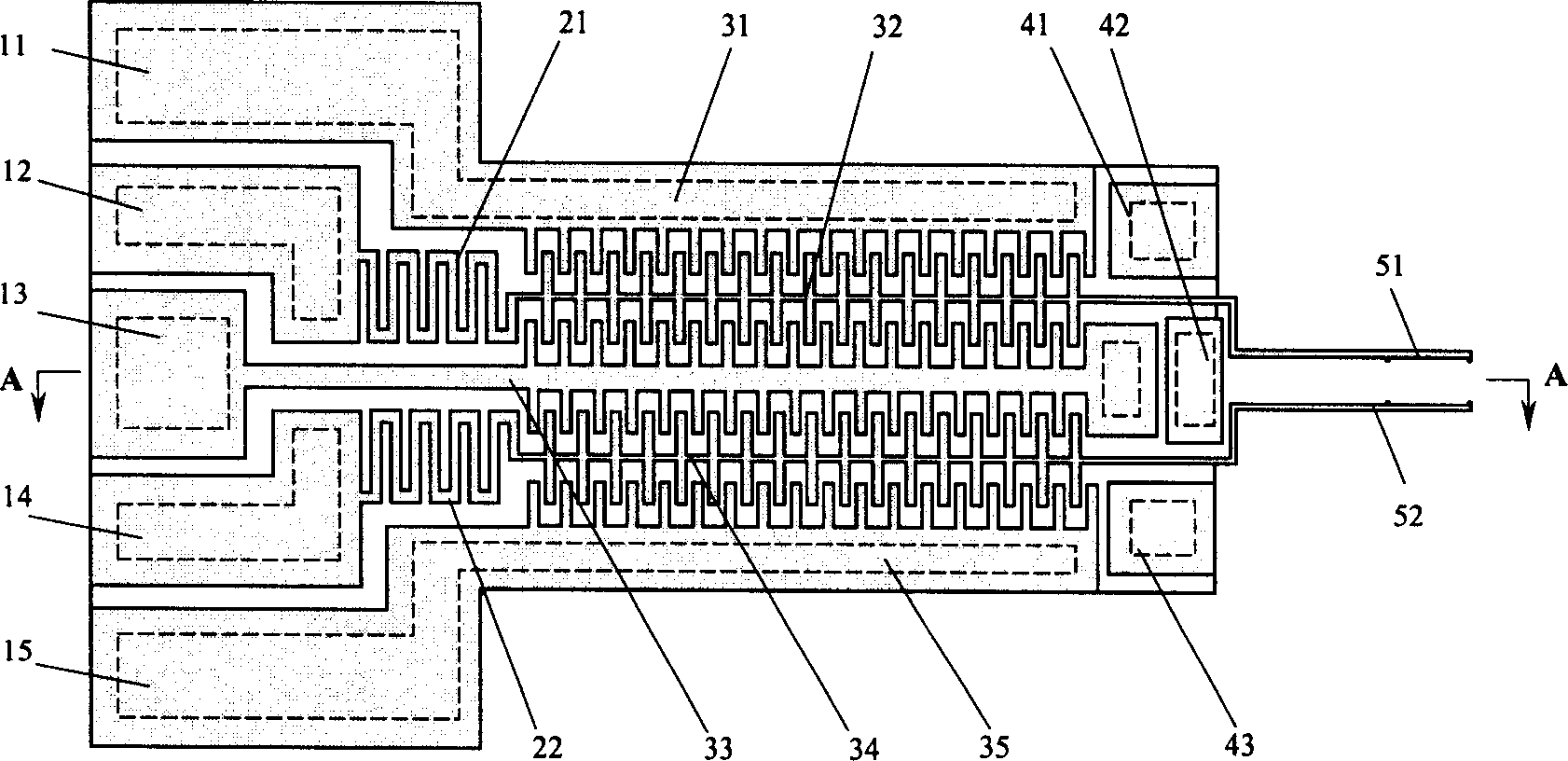
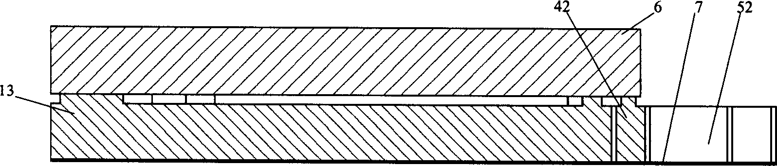
[0024] Such as figure 2 As shown, the present invention is a planar structure as a whole, consisting of driving electrodes 11, 12, 13, 14, 15, flexible structures 21, 22, moving comb teeth 32, 34, fixed comb teeth 31, 33, 35, limit blocks 41, 42, 43, micro clamping arms 51, 52, bottom plate 6, metal bonding layer 7 and other parts. Drive electrodes 12 and 14 are respectively connected to flexible structures 21 and 22, and as their fixed ends, the flexible structure is a continuous S-shaped structure; drive electrodes 11, 13 and 15 are connected to fixed comb teeth 31, 33, 35; flexible structure 21 and 22 are connected with moving comb teeth 32 and 34 respectively; Moving comb teeth 32 and 34 are respectively a part of micro-clamping arms 51 and 52; Limiting blocks 41, 42 and 43 are isolated structures distributed between micro-clamping arms 51 and 52 52 on both sides; driving electrodes (11, 12, 13, 14, 15), fixed comb teeth (31, 33, 35), and position-limiting structures (41...


PUM


Abstract

An electrostatically acturated miniature clamper is composed of a drive electrode, a flexible structure which is a continuous S-shaped one connected between the drive electrode and a movable comb, the movable comb, a fixed comb, a limit block, a miniature clamping arms and a bottom plate, and features that the static electricity is used as the powr source. Its advantages are high response speed and clamping force, and easy control.

Description

technical field [0001] The invention relates to an electrostatically actuated micro-gripper, which is used for micro-operating systems, micro-robots, micro-assembly, micro-welding, and relocation of tiny objects such as cells in bio-genetic engineering, belonging to micro-electro-mechanical systems (MEMS: Microelectro-mechanical systems) Systems) field. Background technique [0002] Micro-electromechanical system (MEMS) refers to a micro-system that can be mass-produced and integrates micro-mechanisms, micro-sensors, micro-actuators, signal processing and control circuits, as well as interfaces, communications and power supplies. MEMS can not only reduce system cost, but also can accomplish many tasks that traditional large-scale electromechanical systems cannot accomplish, such as flexible manipulation of microscopic objects. Microgripper is a key component of MEMS and a basic tool for communicating the macroscopic and microscopic worlds. It has broad application prospect...

Claims


Application Information

Patent Timeline
IPC IPC(8): B25J7/00B81B3/00
Inventor 李玉和李勇李庆祥訾艳阳
Owner TSINGHUA UNIV
Why Eureka
Try Eureka