Electromagnetic coil and its manufacturing method and coil form

A coil bobbin and electromagnetic coil technology, applied in the direction of inductance/transformer/magnet manufacturing, electromagnet, transformer/inductor coil/winding/connection, etc., can solve problems such as short circuit and partial short circuit

Inactive Publication Date: 2003-04-23
FUJIKOKI MFG CO LTD
View PDF0 Cites 12 Cited by
  • Summary
  • Abstract
  • Description
  • Claims
  • Application Information

AI Technical Summary

Problems solved by technology

[0005] When the electromagnetic coil 1 is used for a long time, the air in the spaces 24a to 24d will expand and contract repeatedly, and sometimes

Method used


Image

  • Electromagnetic coil and its manufacturing method and coil form
  • Electromagnetic coil and its manufacturing method and coil form
  • Electromagnetic coil and its manufacturing method and coil form

Examples


Embodiment Construction

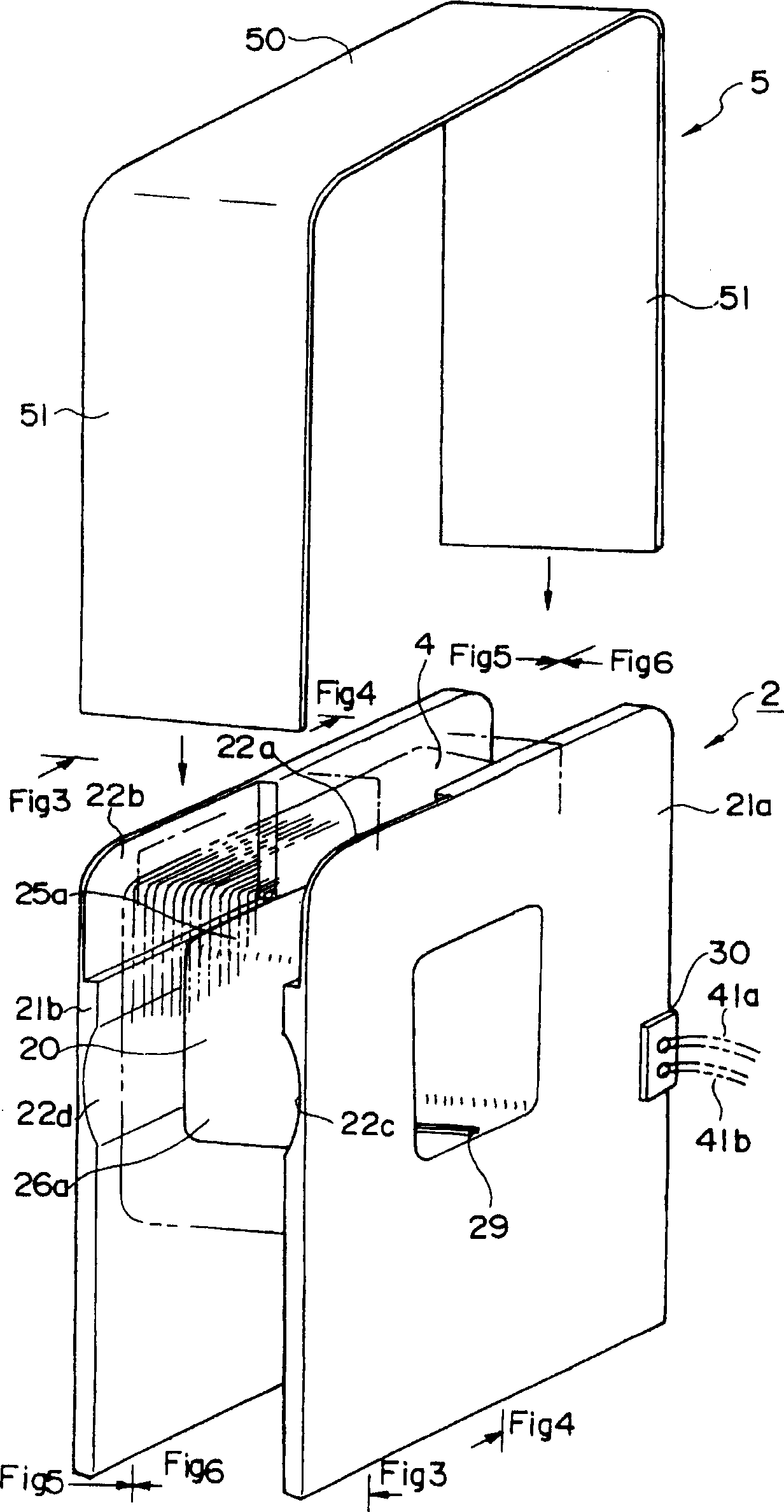
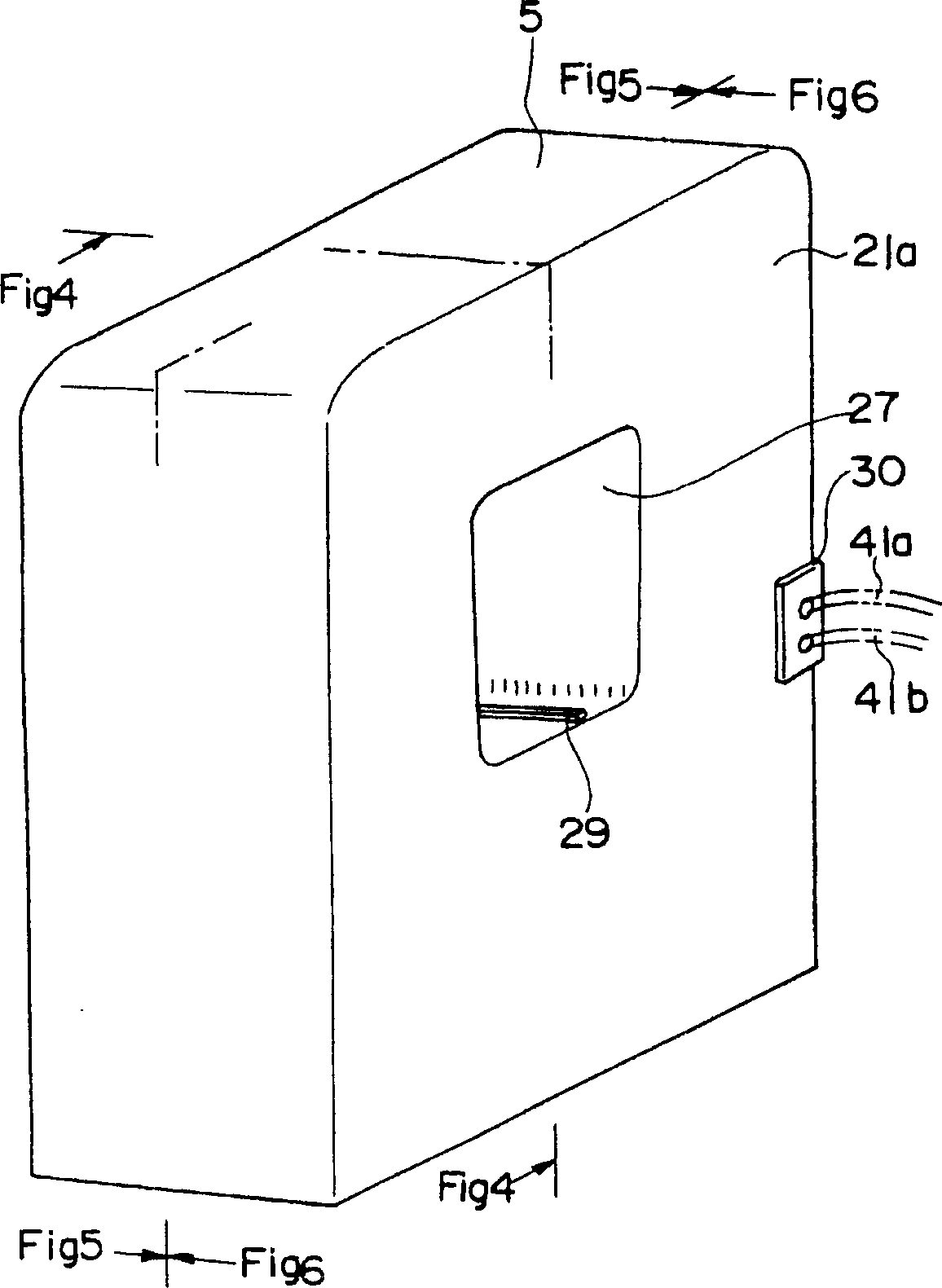
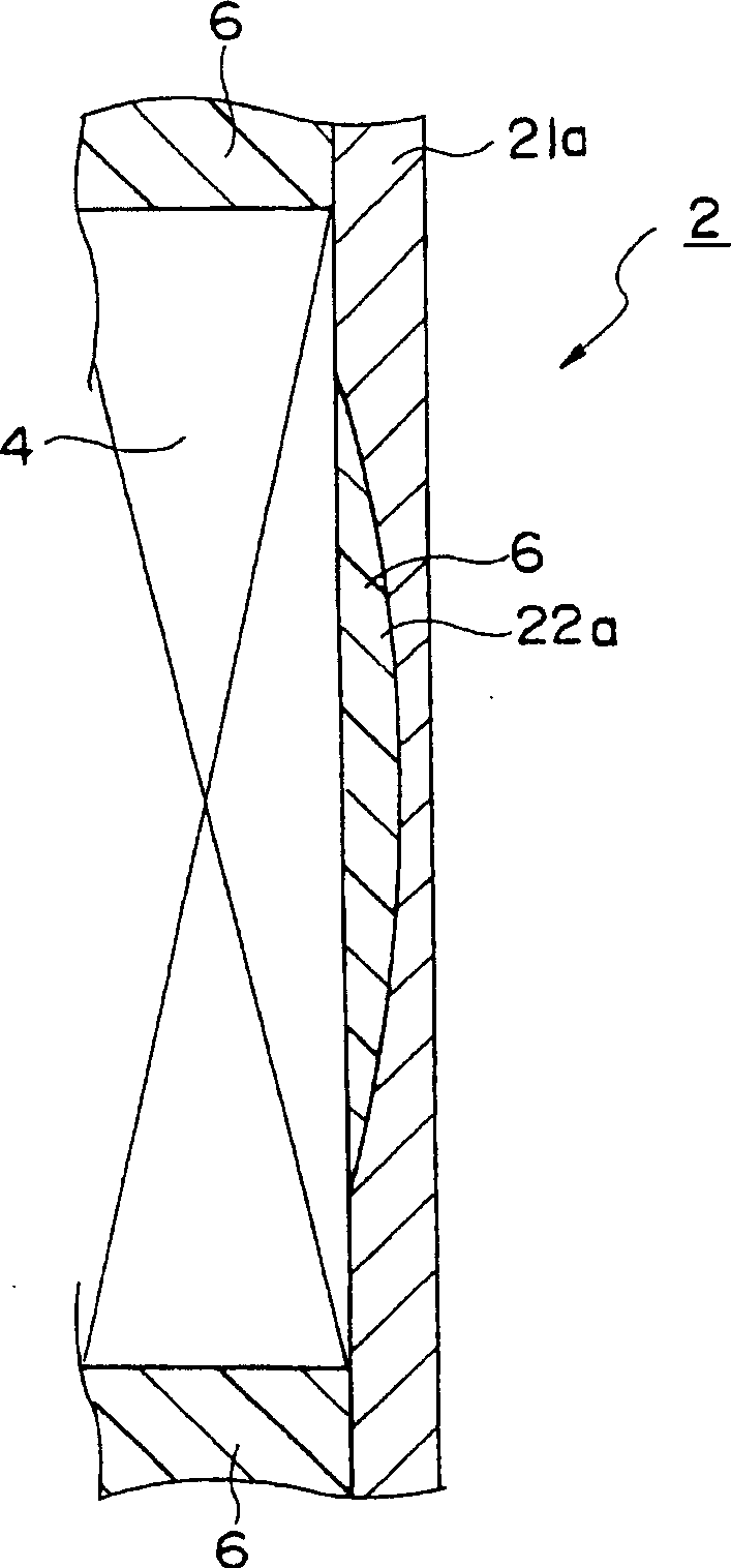
[0023] use below Figure 1 to Figure 6 The structure of the electromagnetic coil of the present invention will be described. figure 1 It is an exploded perspective view illustrating an outline of a bobbin structure forming an electromagnetic coil according to an embodiment of the present invention, figure 2 It is the appearance perspective view of the electromagnetic coil of the embodiment of the present invention, image 3 Is to illustrate the structure of the electromagnetic coil of the present invention figure 1 The enlarged view of the main part of the section along the Fig3-Fig3 section, Figure 4 Is to illustrate the structure of the electromagnetic coil of the present invention figure 1 and figure 2 The longitudinal section along Fig4-Fig4 section, Figure 5 Is to illustrate the structure of the electromagnetic coil of the present invention figure 1 and figure 2 The left longitudinal sectional view along Fig5-Fig5 section, Figure 6 Is to illustrate the s...


PUM


Abstract

To provide an electromagnetic coil that can be used for a long period in an electric motor, solenoid-controlled valve, electromagnetic actuator, etc. This electromagnetic coil is composed of a coil bobbin 3, a coil 4, and a coil case 5. The coil 4 is sealed with a molding resin. Recessed sections 22a, 22b, 22c, 22d, etc., up to the outer peripheral surfaces 25a, 26a, etc., of a core 20 are formed on the internal side faces of the flanges 21a and 21b of the coil bobbin 2. In addition, the molding resin 6 which seals the periphery of the winding 4 is packed in the internal space between the flanges 21a and 21b of the bobbin 2 and the coil case 5, recessed sections 22a, 22b, 22c, 22d, etc., of the flanges 21a and 21b, and the space (not shown in the picture.) formed between the outer peripheral surfaces 25a, 26a, etc., of the core 20 and the coil 4 through vacuum defoaming treatment using the casting method.

Description

technical field [0001] The invention particularly relates to an electromagnetic coil used in an electric motor, an electromagnetic control valve, an electromagnetic transmission device and the like, a manufacturing method thereof, and a coil bobbin. Background technique [0002] Such as the longitudinal section of the electromagnetic coil Figure 7 and in with Figure 7 Longitudinal Sectional View of Orthogonal Surface Figure 8 As shown, the existing electromagnetic coil 1 includes: a bobbin 2, which has a substantially square hollow core 20, and a pair of flanges 21a, 21b opposite and parallel to each other are formed at both ends of the core 20; a winding 4, It consists of an enameled wire wound on the winding core 20 of the bobbin 2; The winding 4 wound around the outer periphery of the winding core 20 of the bobbin 2 is sealed with a sealing resin 6 . [0003] But in the current electromagnetic coil 1, when the outer circumference of the winding core 20 of the bobbin ...

Claims


Application Information

Patent Timeline
IPC IPC(8): F16K31/06H01F7/06H01F27/25H01F27/32H01F41/02
CPCH01F7/06H01F27/25H01F27/327
Inventor 大关尚宏今井正幸桦山正
Owner FUJIKOKI MFG CO LTD
Why Eureka
Try Eureka