Hot rolling thin strip

A steel strip, thin steel technology, used in metal rolling, metal rolling, metal rolling stands, etc.

Inactive Publication Date: 2003-04-30
CASTRIP
View PDF0 Cites 7 Cited by
  • Summary
  • Abstract
  • Description
  • Claims
  • Application Information

AI Technical Summary

Problems solved by technology

[0004] Strip crimp is affected by strip tension and in some applications it is possible to control curl defects by utilizing greater strip tension
However, it is not always possible to utilize large stretches in very thin steel strips at high temperatures

Method used


Image

  • Hot rolling thin strip
  • Hot rolling thin strip
  • Hot rolling thin strip

Examples


Embodiment Construction

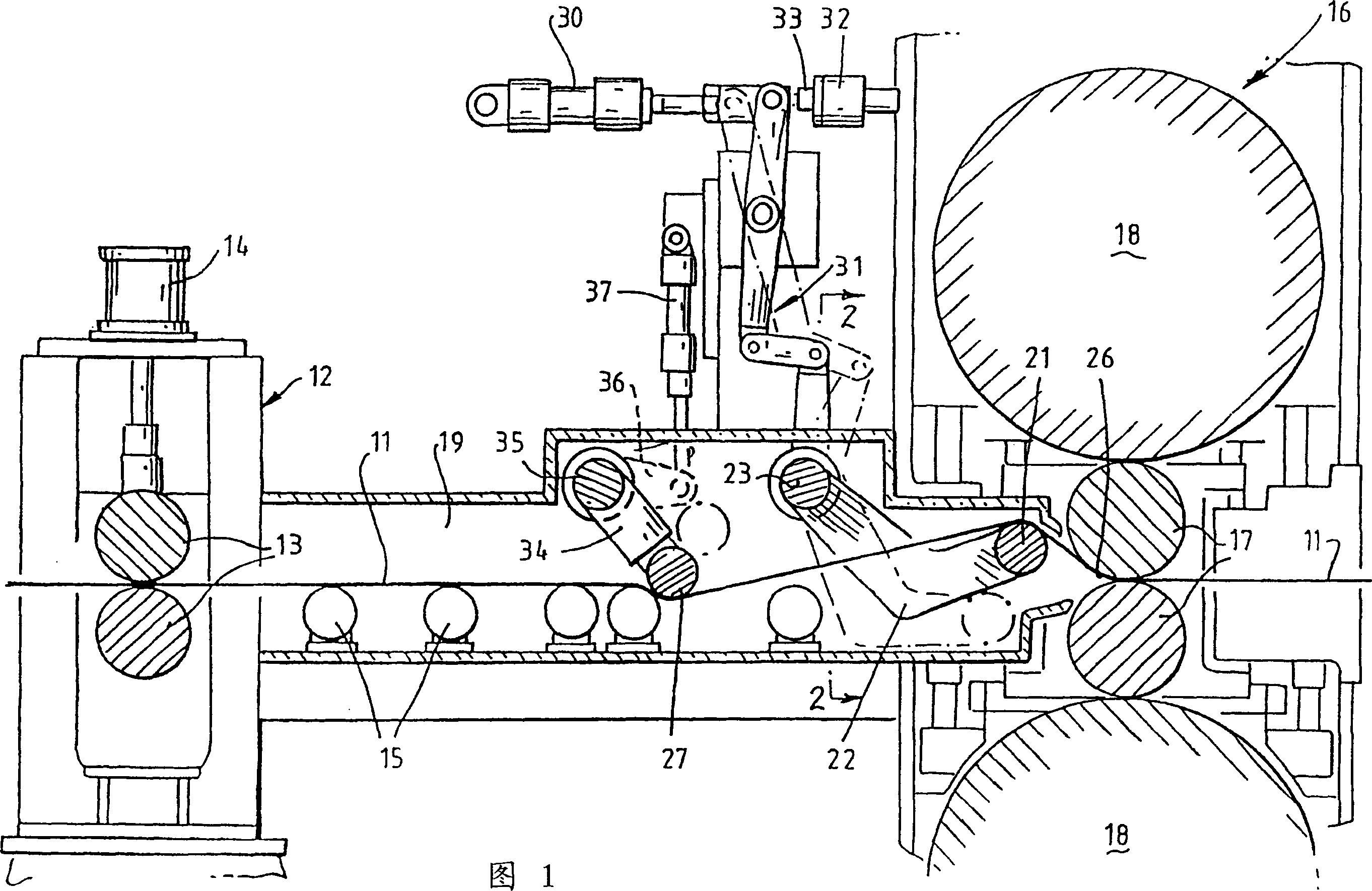
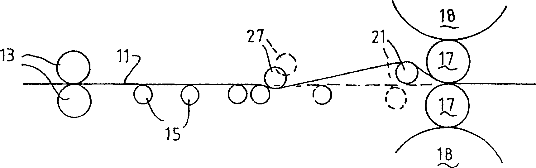
[0017] In the shown rolling mill arrangement, a thin steel strip 11 passes through a pinch roll stand 12 comprising a pair of pinch rolls 13 to which a strip clamping force is applied by a pair of hydraulic cylinder units 14 , a hydraulic cylinder unit 14 is provided on each side of the pinch roll frame.

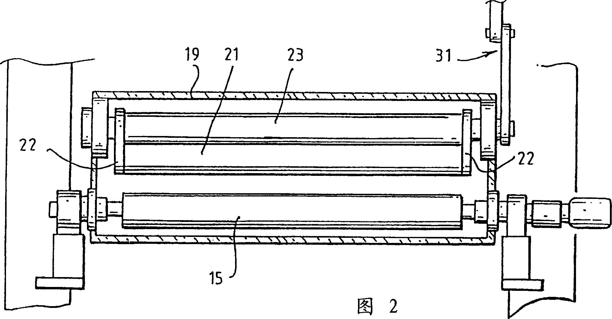
[0018] After passing through the pinch roll stand 12, the strip 11 is supported on a table formed by a series of rollers 15, through which the strip is conveyed to a rolling mill 16 comprising a pair of rollers arranged one above the other. One upper work roll 17 and a pair of upper and lower backup rolls 18 . The strip thinning force is applied between the work rolls 17 through hydraulic cylinder units (not shown), which are arranged on both sides of the rolling mill and act through the upper pressure roll 18 . Between the pinch roll stand 12 and the rolling mill stand 16 the steel strip is held in a sealed casing 19 .

[0019] According to the invention, the apparatus co...


PUM

PropertyMeasurementUnit
diameteraaaaaaaaaa

Abstract

A thin steel strip is passed through a pinch roll stand comprising pinch rolls to a hot rolling mill comprising work rolls and backing rolls. In advance of rolling mill, the strip passes over support rolls. An anti-crimping guide roll located immediately in advance of the rolling mill is mounted on a pair of rocker structures so as to be rasiable from a lower inoperative position to lift the strip out of a straight line path so as to pass around the anti-crimping roll and to be wrapped about the upper work roll, that roll supports the strip and resists buckling of the strip and the generation of crimping defects.

Description

technical field [0001] The present invention relates to the hot rolling of thin steel strip and has particular but not exclusive application to the in-line hot rolling of thin steel strip produced by twin roll steel strip casters. Background technique [0002] Recent developments in twin roll strip casting have enabled the production of strip thicknesses of the order of 5 mm or less. This steel strip can be further reduced in thickness by thinning in an in-line hot rolling mill as the strip is produced by the casting machine. It has been found that when the thickness of the hot rolled strip is around 3mm or less, significant defects in the strip arise due to the coiling of the strip material as it enters the thinning rolls. This curl defect can be small and appears as a visible curve on the strip surface. However, especially when rolling very thin strips, the coiled portion of the strip becomes folded together before rolling so that this portion of ...

Claims


Application Information

Patent Timeline
Patent Type & Authority Applications(China)
IPC IPC(8): B21B1/46B21B1/22B21B1/26B21B13/22B21B15/00B21B37/28B21B39/00B21B39/08B21B41/10B21B45/00B22D11/06B22D11/12
CPCB21B2001/225B21B39/006B21B45/008B21B39/08B21B37/28B21B2015/0071B21B1/463Y02P70/10B21B1/46
Inventor 加藤平二迈克尔·A·洛佩斯约翰·A·齐格拉尔
Owner CASTRIP
Why Eureka
Try Eureka