Unlock instant, AI-driven research and patent intelligence for your innovation.

System for detecting signal dither and its correcting method

A technology for detecting signals and signals, applied in the direction of digital signal error detection/correction, recording signal processing, optical recording/reproduction, etc., which can solve the effects of circuit saturation or drift, signal jitter quantization, and the inability to provide servo systems in real time And other issues

Inactive Publication Date: 2003-06-11
IND TECH RES INST
View PDF0 Cites 11 Cited by
  • Summary
  • Abstract
  • Description
  • Claims
  • Application Information

AI Technical Summary

Problems solved by technology

[0005] However, for high-speed optical drive data streams, the frequency of the data stream is already quite high. The pulse counting method requires a higher-speed counting pulse to detect signal jitter, and the resolution of signal jitter is limited by the counting pulse. Frequency of
The fast integration method also requires a large bandwidth and is easily affected by circuit saturation or drift
Therefore, for the adjustment of the servo system of high-speed optical drives, the third detection method is generally adopted, and the signal jitter is directly observed by the oscilloscope, but the signal jitter cannot be quantified only by the naked eye, and the servo system adjustment control cannot be provided in real time. Parameter reference

Method used


Image

  • System for detecting signal dither and its correcting method
  • System for detecting signal dither and its correcting method
  • System for detecting signal dither and its correcting method

Examples


Embodiment Construction

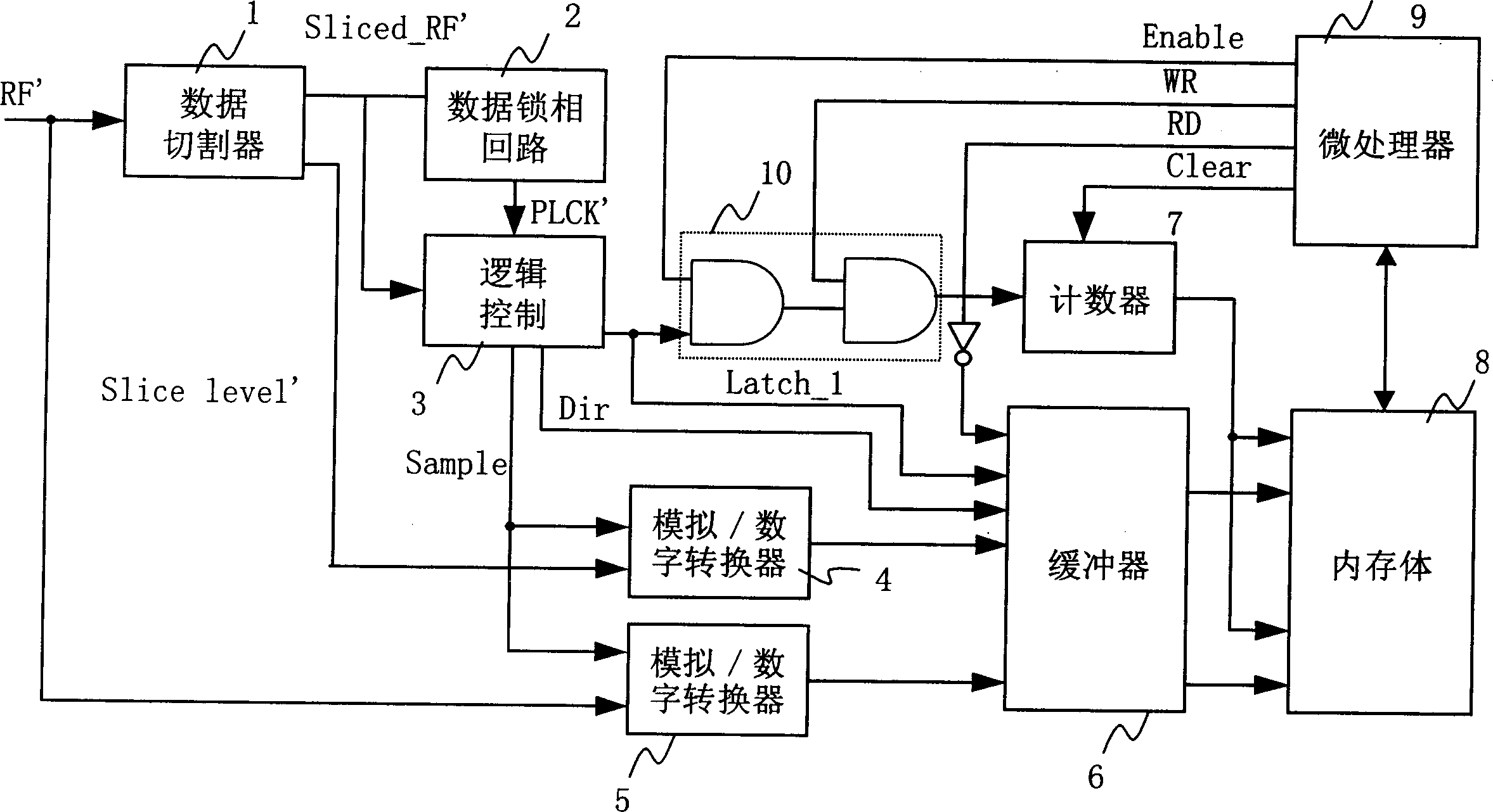
[0017] According to the system for detecting signal jitter and the correction method thereof disclosed in the present invention, first, according to the DVD specification, the definition of signal jitter (jitter) is that after the disc data read by the optical drive read head is amplified by the pre-stage, an analog signal is generated. The radio frequency (RF) signal, and the analog radio frequency signal is encoded into a binary signal (Binary signal) by the cutter (Slicer), and becomes a slicing signal (Sliced_RF), and the time interval between the upper and lower edges of the slicing signal is relative in the period of the reference pulse (PLL clock signal; PLCK). And according to the optical characteristics, it is known that the radio frequency (RadioFrequency; RF) signal is in the vicinity of its center level, and the amplitude change and the time change are approximately proportional, so this voltage difference can be equalized as a time difference. When there is signal...


PUM


Abstract

The system is utilized to detect the time interval between the upper edge, the lower edge of the high-speed data stream read out by the optical drive and the referent pulse (so called signal dithering). The radio frequency signal read out by the optical head is near the central standard position of the analog radio frequency signal. It is the approximate the proportional relation between the amplitude variation and the image variation. The dithering value is calculated out by equalizing the difference of the voltage to the difference of the time.

Description

technical field [0001] The invention belongs to a system for detecting signal jitter and a correction method thereof, which are applied to detecting the signal jitter of a data stream of a high-speed digital system, and in particular relates to a device for detecting signal jitter using a voltage difference into a time difference and method. Background technique [0002] In the past few years, "jitter" has become a signal characteristic that many engineers attach great importance to, because in high-speed digital systems, the "rise times" of the signal have changed. As the system's operating speed increases by one megabit per second (Mbps), a slight change in the rising or falling edge of a signal will have a bigger impact. The "skew" (skew) or "phase error" (data jitter) of the signal waveform not only affects the "integrity" (integrity) of the data and the "setup time" and "hold time" of the signal voltage ( hold time), it will also make it more difficult for the system ...

Claims


Application Information

Patent Timeline
IPC IPC(8): G11B7/00G11B20/00G11B20/10G11B20/18
Inventor 王金印王吉祥黄兆铭卢树台
Owner IND TECH RES INST