Bus-controlled parallel uninterrupted power source (UPS) system

A technology of bus control and control system, which is applied in the direction of emergency power supply arrangements, collectors, electric vehicles, etc., can solve problems such as poor power supply quality, poor power supply quality, and power supply interruption, and achieve high real-time data processing capabilities and good maintainability , Improve the effect of dynamic response speed

Inactive Publication Date: 2003-06-11
GUANGDONG ZHICHENG CHAMPION GROUP
View PDF0 Cites 57 Cited by
  • Summary
  • Abstract
  • Description
  • Claims
  • Application Information

AI Technical Summary

Problems solved by technology

[0002] Due to various harmonic interferences, flashes, surges, etc. in the actual power supply network, the power supply quality is poor and unstable; in addition, due to factors such as lightning strikes, power supply line failures, accidents, etc. Cause the interruption of power supply; for ordinary households, these effects will not cause serious consequences, but for some special industries and departments, such as banking systems, securities companies, telecommunications departments, railway and civil aviation signaling systems, computer Network systems, large-scale data processing and switching centers, national defense and other industries and departments, it is difficult to imagine what kind of consequences will occur once the power supply system is interrupted or the power supply system is disturbed by poor power supply quality, causing most losses; with the progress of the times With the development of society and society, the power users in various departments and fields of the national economy have higher and higher requirements for the power supply quality of the power supply system. However, most of the requirements are difficult to meet by the mains power grid power supply system. -Uninterruptible Power Supply) follows the needs of the society; however, as a single power electronic device, the reliability of its work cannot be absolute. When there is always a failure, the failure rate during its working life It is impossible to reach zero; once the UPS is damaged, the load power supply will still be interrupted; in order to further improve the reliability of the load power supply, and at the same time expand the power supply capacity, efforts are being made to study the parallel operation control technology of UPS at home and abroad. , the parallel control technology has experienced the development fr...

Method used


Image

  • Bus-controlled parallel uninterrupted power source (UPS) system
  • Bus-controlled parallel uninterrupted power source (UPS) system
  • Bus-controlled parallel uninterrupted power source (UPS) system

Examples


Embodiment Construction

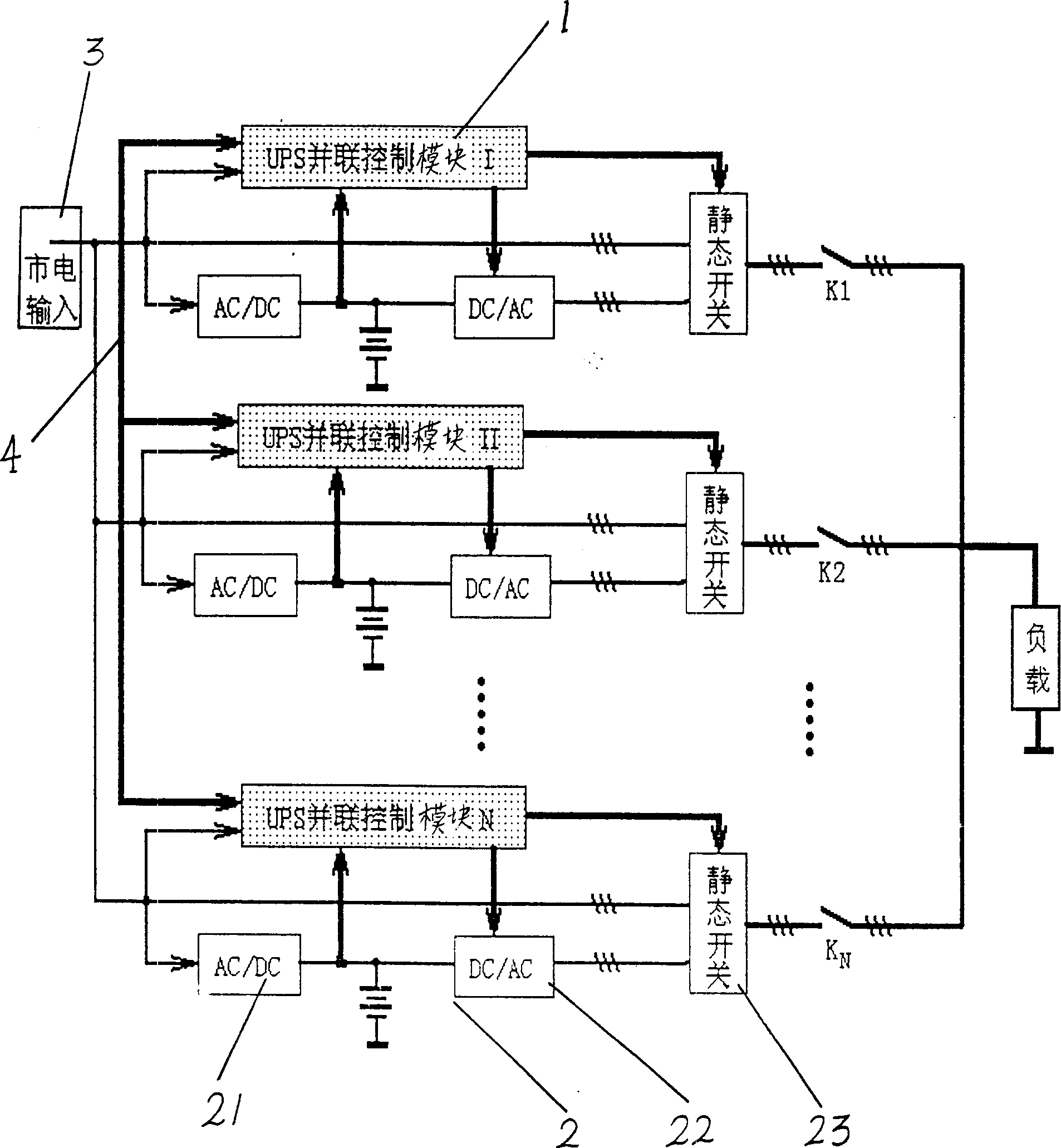
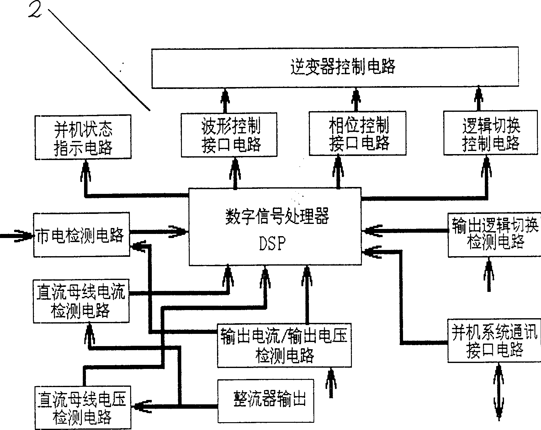
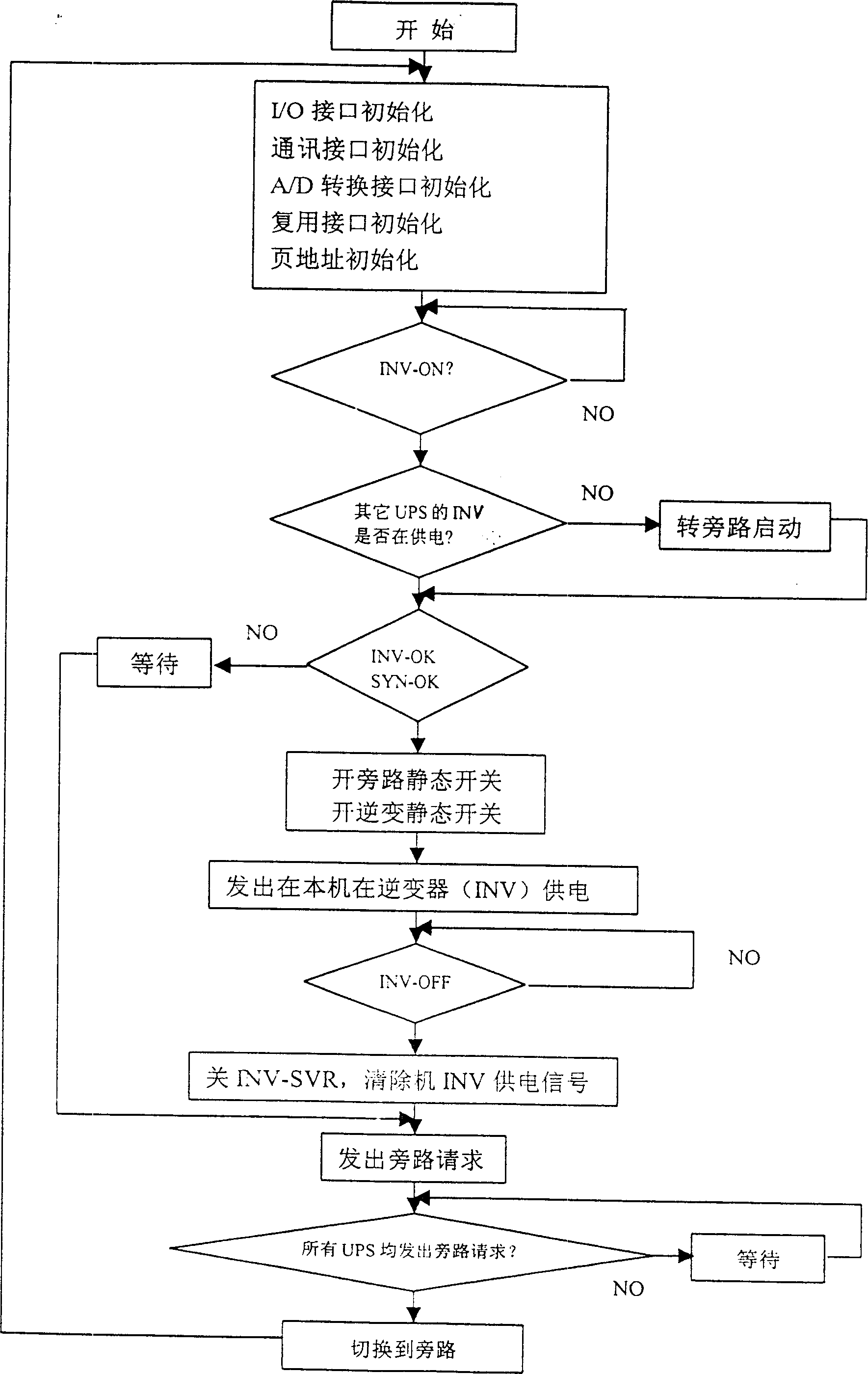
[0029] See attached Figure 1-4 , the UPS parallel control system 1 of the present invention is placed in the UPS2 and connected to the UPS2, and is connected to each other through the data bus 4; wherein, the UPS parallel control system 1 includes a digital signal processor DSP as a core and a waveform control interface of a peripheral functional unit circuit circuit, phase control interface circuit, logic switching control circuit, parallel machine state indication circuit, DC bus current detection circuit, DC bus voltage detection circuit, output current and output voltage detection circuit, mains power detection circuit, parallel system communication interface circuit, output logic switching detection circuit; and, the digital signal processor DSP of the UPS parallel control system 1 respectively passes through the mains power detection circuit, the DC bus current detection circuit, the DC bus voltage detection circuit, the output current and output voltage detection circui...


PUM


Abstract

Parallel UPS system controlled by bus relates to power source equipment technology with the following scheme: UPS parallel control system is put in and connected with UPS, realizing N+1 redundant parallel operation and every UPS will supply electricity to load and shares the load to meet the requirement of parallel operation having very high real time data process capability to ensure the real time control and reliability of UPS parallel control system increased greatly.

Description

Technical field: [0001] The invention relates to the technical field of power supply equipment, in particular to a bus-controlled parallel uninterruptible power supply (UPS) system. Background technique: [0002] Due to various harmonic interferences, flashes, surges, etc. in the actual power supply network, the power supply quality is poor and unstable; in addition, due to factors such as lightning strikes, power supply line failures, accidents, etc. Cause the interruption of power supply; for ordinary households, these effects will not cause serious consequences, but for some special industries and departments, such as banking systems, securities companies, telecommunications departments, railway and civil aviation signaling systems, computer Network systems, large-scale data processing and switching centers, national defense and other industries and departments, it is difficult to imagine what kind of consequences will occur once the power supply system is interrupted or ...

Claims


Application Information

Patent Timeline
IPC IPC(8): H02J7/00H02J9/00
Inventor 周志文康勇陈息坤段善旭李民英
Owner GUANGDONG ZHICHENG CHAMPION GROUP
Why Eureka
Try Eureka