
Duplex type machine for straightening and cutting off reinforcing steel bars

A technology of cutting machine and cutting mechanism, which is applied in the field of wire rod processing or processing, can solve the problems of high pay-off frame, waste of scrap ends, poor straightening quality, etc., and achieve reasonable and compact structure, wide straightening range, straightening high quality effect

Inactive Publication Date: 2003-07-23
曲海涛
View PDF0 Cites 23 Cited by
  • Summary
  • Abstract
  • Description
  • Claims
  • Application Information

AI Technical Summary

Problems solved by technology

But up to now, the existing steel bar straightening and cutting machine has the following problems in varying degrees: one, at present, each plate of steel bar is very big and heavy, and the pay-off frame needs to be done very big, so it is very big for the installation. Difficulties caused by materials, especially loose bundles of wire rods, even with lifting equipment, it is also difficult to load materials
2. In the prior art, the distance between the straightening roller (straightening element) of the straightening mechanism of the steel bar straightening and cutting machine in the direction of the straightening swivel axis is fixed, regardless of the large diameter and small diameter, high strength and low The high-strength steel bar has only one deformation zone of constant size, which has poor adaptability to steel bars of different diameters and different strengths, and the straightening effect is not good
3. The contact angle between the axis of the straightening roller installed obliquely on the straightening swivel and the axis of the steel bar is fixed. If the inclination angle is designed according to the design of the large-diameter steel bar, the contact angle of the straightened small-diameter steel bar will change. The area becomes smaller, so that in the straightening process, the straightening rollers will press out evenly distributed small bends on the surface of the steel bar, making the straightening quality very poor
4. The existing steel bar straightening and cutting machines are all completed by a group of rotating straightening mechanisms
During the straightening process, the straightening mechanism can only rotate in one direction, which will distort the axis direction of the steel bar after straightening, especially because the two longitudinal ribs of the hot-rolled ribbed steel bar are higher, and the distortion after straightening is more serious.
5. The cutting mechanism is easy to cut continuously, cutting out the scraps will cause waste
6. The sizing is inaccurate and the cutting error is large

Method used


Image

  • Duplex type machine for straightening and cutting off reinforcing steel bars
  • Duplex type machine for straightening and cutting off reinforcing steel bars
  • Duplex type machine for straightening and cutting off reinforcing steel bars

Examples


Embodiment 1

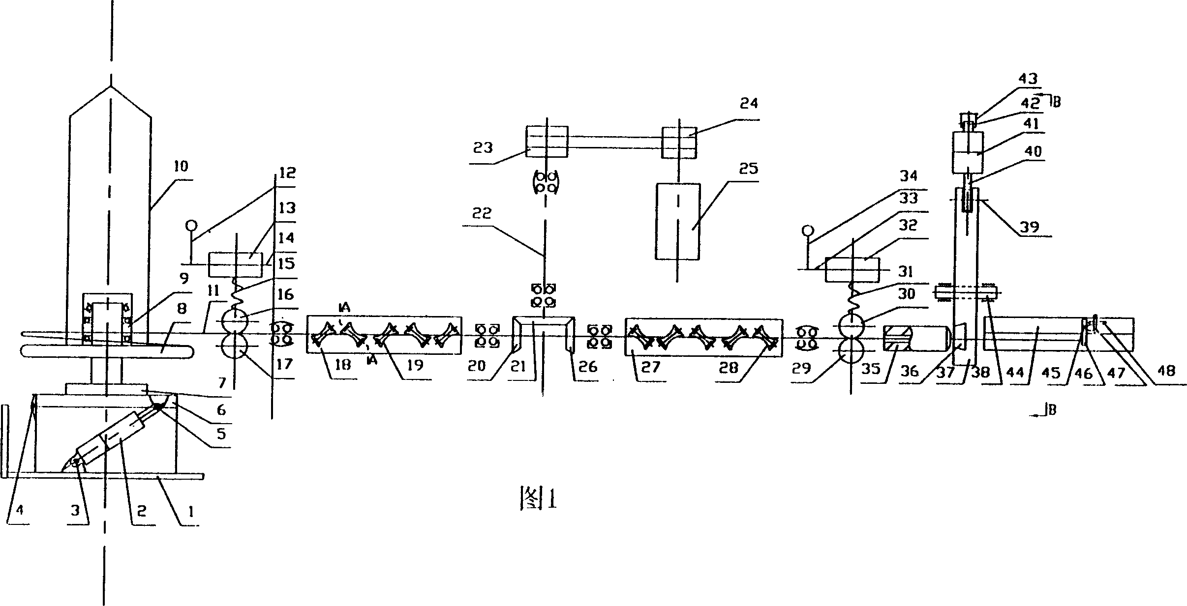
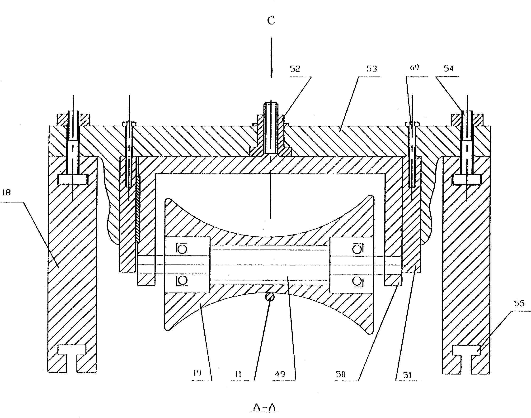
[0017] Accompanying drawing 1 discloses an embodiment of the present invention (see Fig. 1), on pay-off rack base 1 and loam cake 6, winch 3 and 5 are respectively arranged, and base 1 is connected with loam cake 6 with winch 4, oil cylinder 2 is installed on the winches 3 and 5; the upper cover 6 is equipped with a column shaft 7, and a bearing seat 9 is installed on the column shaft 7, and a tray 8 and a core frame 10 are installed on the bearing seat 9; through the hydraulic cylinder 2, the The upper cover 6 is tilted 90 degrees with 4 as the fulcrum, and after the steel bar 11 is installed, the upper cover 6 is returned to its original position by the hydraulic cylinder 2; Figure 4 ). The left end and the right end of the straightening mechanism are provided with clamping mechanism respectively (see Figure 5 ): consisting of lower clamping rollers 17 and 29, upper clamping rollers 16 and 30, clamping springs 15 and 31, eccentric wheels 13 and 32, handle shafts 14 and 33...

Embodiment 2

[0021] Figure 7 It is the second embodiment of the present invention (see example Figure 7 ), motor 73 drives belt pulleys 72,71, and motor 76 drives belt pulleys 75,74 to drive two sets of straightening swivels 18,27 of the straightening mechanism respectively to rotate and straighten in opposite directions with the same rotating speed. The settings and actions of other mechanisms are the same as in Embodiment 1.

Embodiment 3

[0023]In the third embodiment of the present invention, a set of straightening swivels can be removed, and the settings and actions of other mechanisms are the same as in embodiment 1.

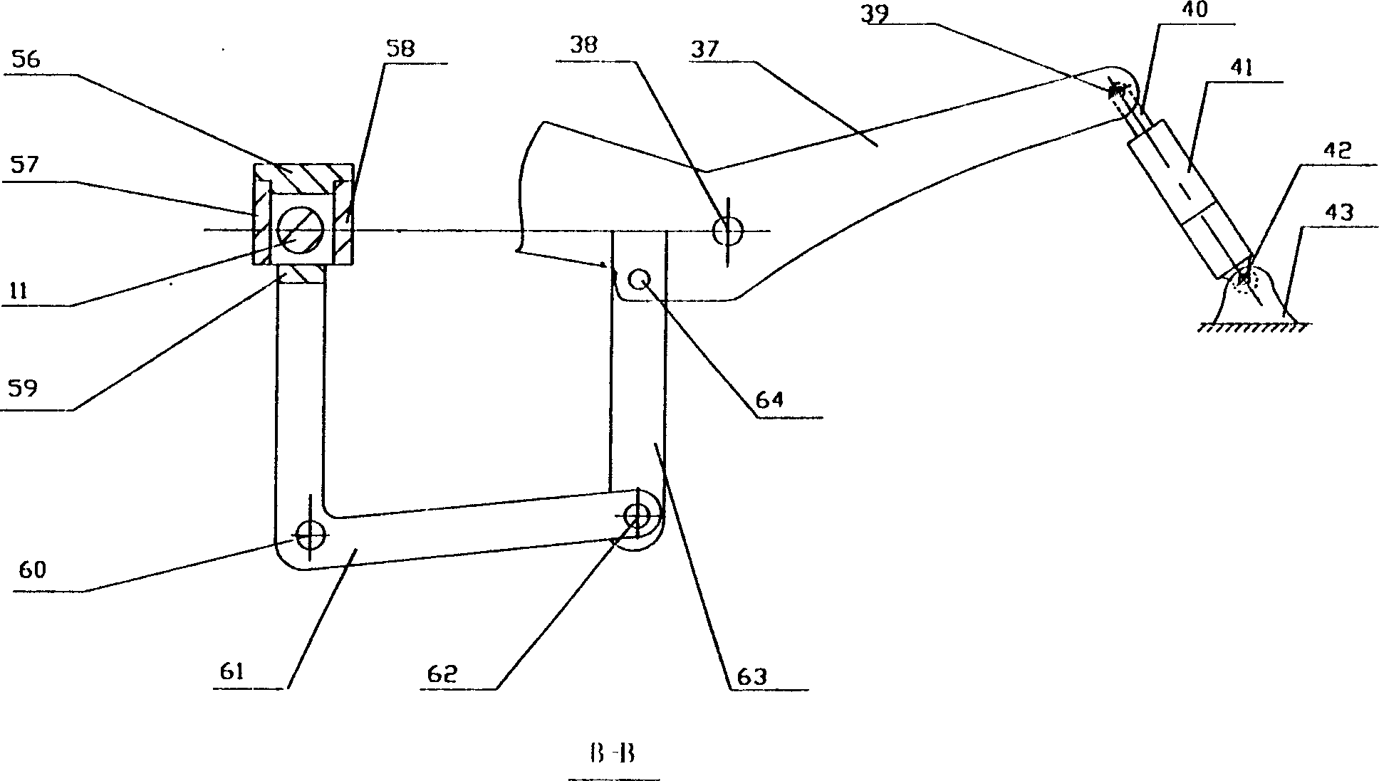
[0024] Its working principle is: when the wire rod 11 is installed on the core frame 10 of the pay-off frame, the double-acting oil cylinder installed on the base 1 and the upper cover 6 will stretch out the piston rod under the action of high-pressure oil, pass through the fulcrums 3 and 5, and go up. The cover 6 uses the fulcrum 4 as the axis to tilt the column shaft 7 tray 8 bearing seat 9 core frame 10 together with the upper cover 6 for about 90 degrees. After the steel wire rod 11 is installed, the piston rod returns to the original position under the action of high-pressure oil The pay-off frame is in a vertical state. Tray 8 bearing seats 9 core frames 10 rotate on the column shaft 7 during setting-out. Upper clamping rollers 16 and 30 are passed through handle rods 12 and 34 handle s...


PUM


Abstract

A reinforcing bar straightening and cutting-off machine features that a hydraulic cylinde is arranged in the base of paying out frame for both rotating and inclining the paying out frame, two sets ofstraightening mechanism are used for preventing axial torsion of reinforcing bar by rotating oppositely, its straightening rotor has T-shaped slot and circular guide sleeve for regulating the straightening roller, and a hydraulic cylinder is used as the power source of cutting off. Its advantages are easy feeding, compact structure, high straightening quality and precise sizes.

Description

Technical field [0001] The invention relates to the technical field of wire rod processing or treatment, in particular to a compound steel bar straightening and cutting machine. Background technique [0002] my country has decades of history in developing and producing steel bar straightening and cutting machines, especially in recent years new products continue to emerge. But up to now, the existing steel bar straightening and cutting machine has the following problems in varying degrees: one, at present, each plate of steel bar is very big and heavy, and the pay-off frame needs to be done very big, so it is very big for the installation. Difficulties are caused by materials, especially loose bundles of wire rods, even if there is a lifting device to load materials, it is also very difficult. 2. In the prior art, the distance between the straightening roller (straightening element) of the straightening mechanism of the steel bar straightening and cutting machine in the dir...

Claims


Application Information

Patent Timeline
IPC IPC(8): B21D3/02B21F11/00
Inventor 曲海涛
Owner 曲海涛
Learn More