Wefting inserter for air-jet loom

A technology of weft insertion device and air-jet loom, which is applied in looms, textiles, textiles and papermaking, etc., and can solve problems such as cost defects

Inactive Publication Date: 2003-07-30
TOYOTA IND CORP
View PDF2 Cites 11 Cited by
  • Summary
  • Abstract
  • Description
  • Claims
  • Application Information

AI Technical Summary

Problems solved by technology

This requires a large power capacitor, which has cost drawbacks com

Method used


Image

  • Wefting inserter for air-jet loom
  • Wefting inserter for air-jet loom
  • Wefting inserter for air-jet loom

Examples


Embodiment Construction

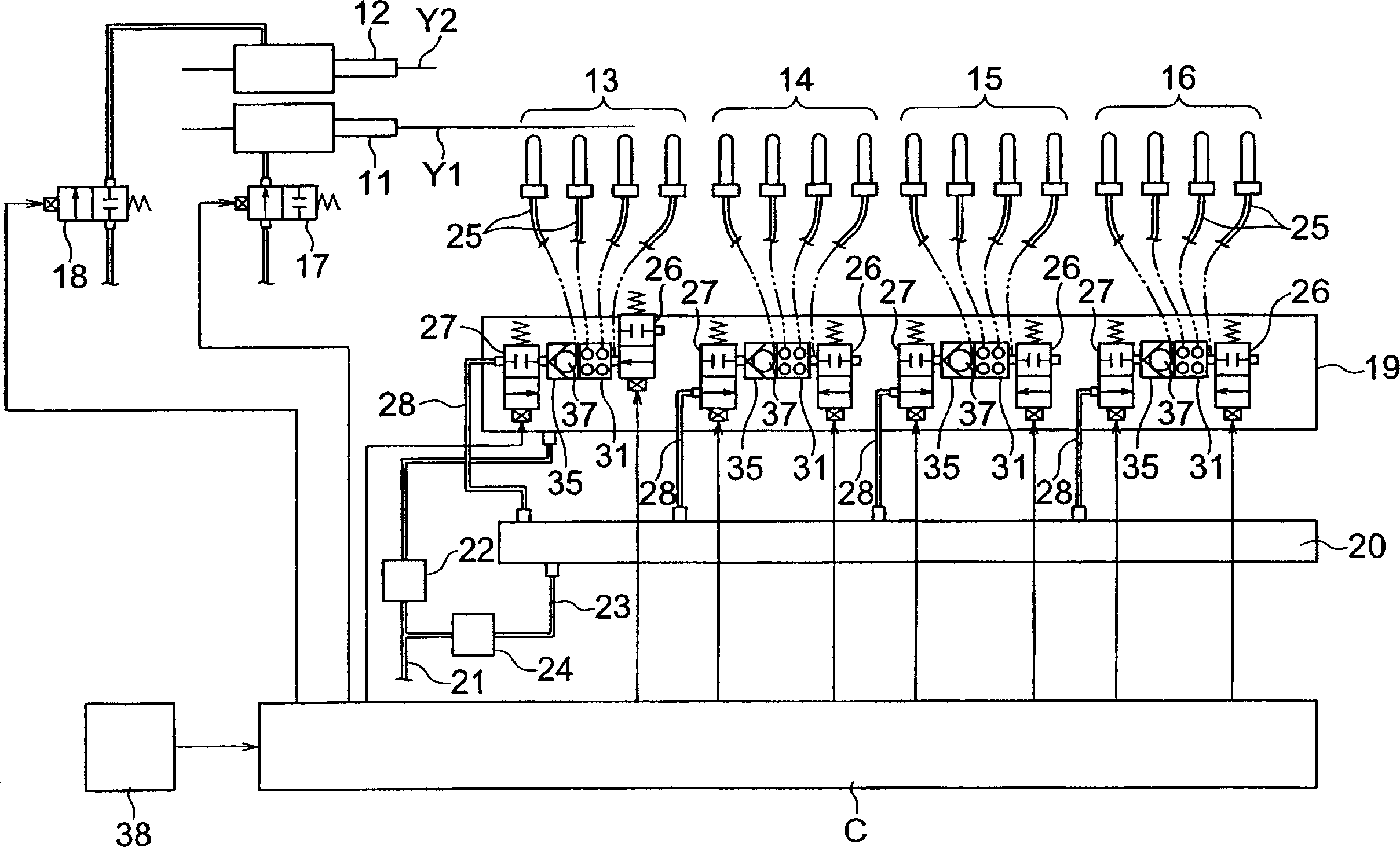
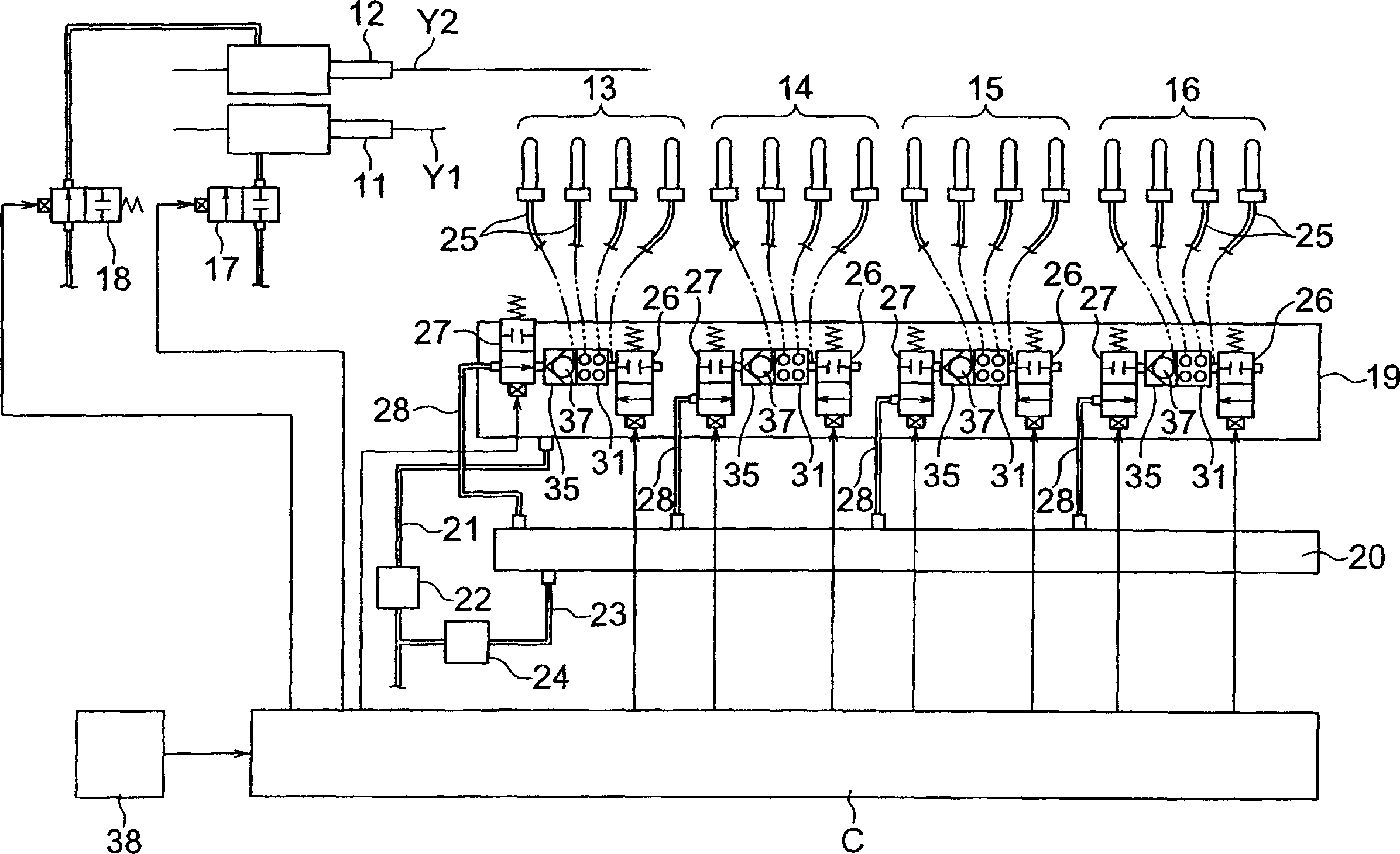
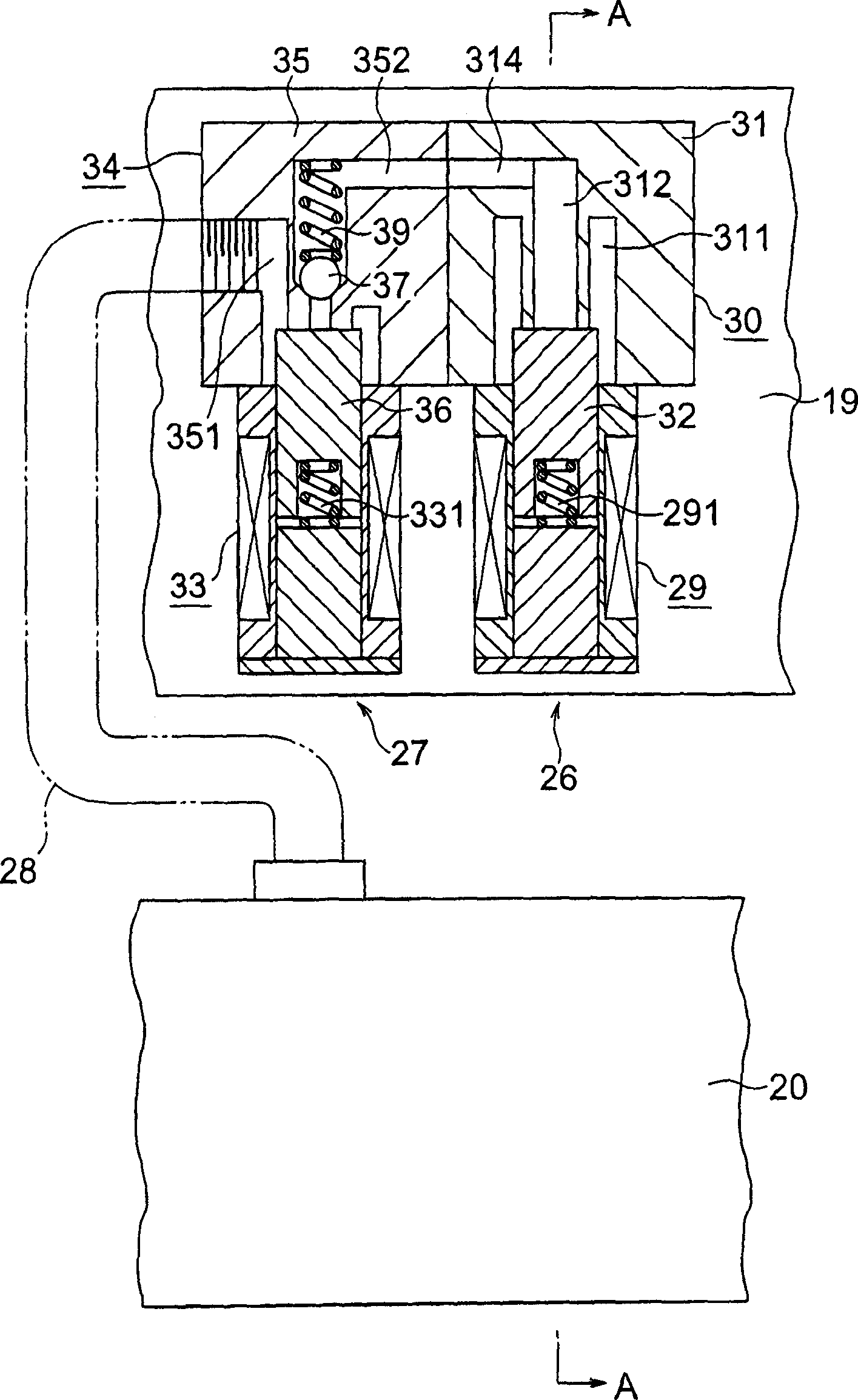
[0029] Combine below Figures 1 to 4 A first embodiment embodying the present invention will be described.

[0030] Such as figure 1 As shown, a pair of weft insertion main nozzles 11 and 12 inject weft yarns Y1 and Y2 into a warp yarn opening (not shown) according to a predetermined weft yarn selection pattern. The weft insertion auxiliary nozzle groups 13, 14, 15 and 16 complete the continuous spraying from the weft insertion main nozzles 11 and 12 sides. The alternate jets draw the weft yarns Y1 and Y2 into the warp openings. Weft insertion main nozzles 11 and 12 are connected to an air tank (not shown) through intermediate electromagnetic on / off valves 17 and 18, and the air tank receives pressurized air provided by a pressurized air source (not shown). The electromagnetic on / off valves 17 and 18 are energized and demagnetized according to the weft selection pattern.

[0031] The weft insertion auxiliary nozzle groups 13 to 16 are provided with pressurized air by a pai...


PUM


Abstract

The present invention provided a picking motion in a jet loom, capable of avoiding a backflow of air and a cost problem. In this picking motion of the jet loom, groups of auxiliary picking nozzles are each connected to an upstream-positioned air tank through electromagnetic on-off valves. And, the groups of auxiliary picking nozzles are each connected to a downstream-positioned air tank through electromagnetic on-off valves. Check valves are each mounted on flow paths located on the downstream sides of the electromagnetic on-off valves. The electromagnetic on-off valves are subjected to excitation and demagnetization control with a control computer. The control computer controls excitation and demagnetization of electromagnetic on-off valves based on information on a rotation angle of the loom which is transmitted from a rotary encoder for detecting the rotation angle of the loom.

Description

technical field [0001] The invention relates to a weft insertion device for an air-jet loom, which inserts wefts through the air-jet action of nozzles. Background technique [0002] As already disclosed in JP58-126344A and JP10-273853A, when weft insertion is performed for multiple weft yarns in an air-jet loom, the air injection pressure from the auxiliary nozzle for weft insertion is controlled for each different kind of weft yarn. set. [0003] In the device disclosed in JP58-126344A, auxiliary nozzles for weft insertion are connected to a single air storage tank through two air supply lines formed by an electromagnetic on / off valve and a throttle valve. [0004] In the weft insertion device disclosed in JP10-273853A, a high-pressure air supply line formed by an ordinary electromagnetic on / off valve and a pressure-selective electromagnetic on / off valve is connected to a high-pressure air tank. In addition, a low-pressure air supply line formed by a conventional solenoid...

Claims


Application Information

Patent Timeline
IPC IPC(8): D03D47/30
CPCD03D47/306D03D47/3053
Inventor 牧野洋一石川洋彦
Owner TOYOTA IND CORP
Why Eureka
Try Eureka