Active control system and method with less magnetic track disalignment caused by disk chatter

A technology for disk drives and data tracks, which is applied to align tracks on a disk, drive/move recording heads, magnetic recording, etc., and can solve problems such as not helping to improve tracking accuracy

Inactive Publication Date: 2003-07-30
DATA STORAGE INST
View PDF5 Cites 13 Cited by
  • Summary
  • Abstract
  • Description
  • Claims
  • Application Information

AI Technical Summary

Problems solved by technology

However, this approach does not help improve seek accuracy

Method used


Image

  • Active control system and method with less magnetic track disalignment caused by disk chatter
  • Active control system and method with less magnetic track disalignment caused by disk chatter
  • Active control system and method with less magnetic track disalignment caused by disk chatter

Examples


Embodiment Construction

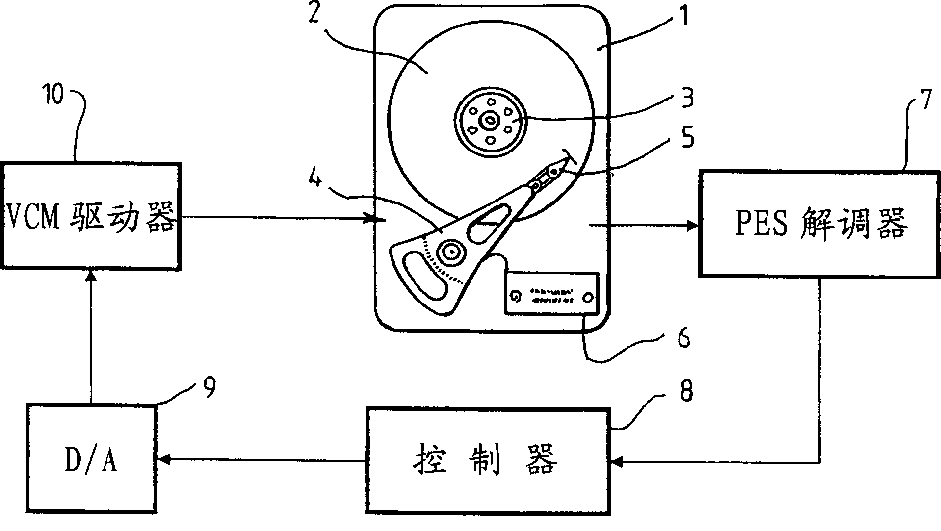
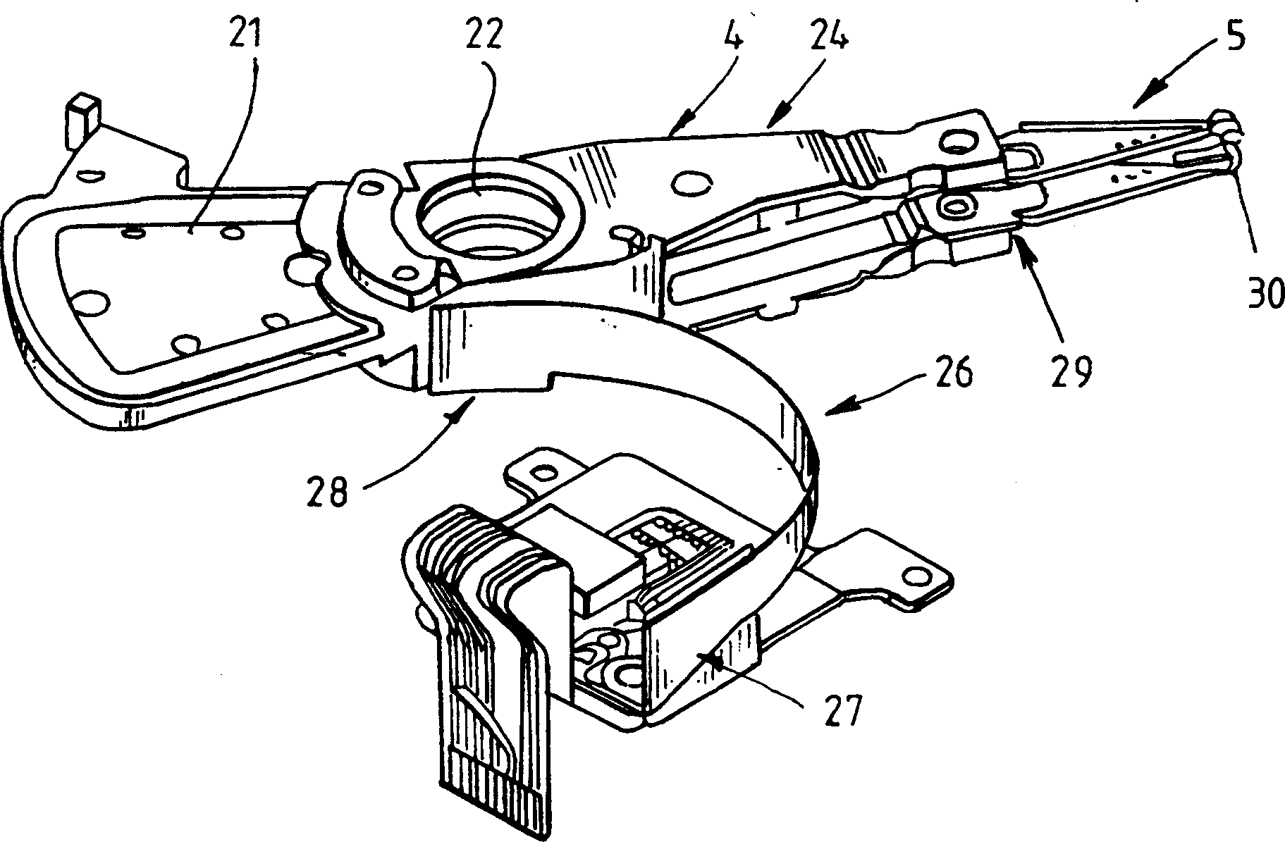
[0049] now refer to Figure 1a , shows a disk drive (1) with a plurality of rotatable disks (2) that can be rotated by a spindle motor (3). A rotary actuator (4) moves a suspension (5) for supporting the R / W head, which accesses concentric data tracks on the disk surface. The signal picked up by the R / W head is amplified and filtered. This signal is sent to a circuit (7) which detects the position error signal (PES) and the track number. For example, the R / W head may be a magnetoresistance (MR) head or a giant magnetoresistance (GMR) head, so in such an embodiment the PES obtained from the PES demodulator (7) is usually linearized. The linearized PES signal and track number are sent to the servo controller (8), which calculates the desired control signal in digital format and converts the control signal through a digital-to-analog converter (DAC) (9). output to a voice coil motor (VCM) drive circuit (10). Depending on servo loop bandwidth and access speed requirements, a se...


PUM


Abstract

The present invention relates to controlling an actuator for positioning a read / write head in storage devices such as disk drives. More specifically, the invention relates to using a sensor to detect the disk vibration amplitude perpendicular to the disk surface, and using feed forward control to cancel or counteract the tendency of the read / write head to deviate off-track due to disk vibration. Various approaches are proposed to detect the disk vertical vibration.

Description

field of invention [0001] The present invention relates to controlling a head positioning actuator in a storage device such as a disk drive by feed-forward control in order to reduce or counteract off-track deviation of the read / write head induced by disk chatter. More specifically, the present invention relates to the use of sensors to detect disk vibrations perpendicular to the disk surface and the use of feedforward control to cancel or counteract head off-tracking caused by disk vibrations. Various methods have been proposed for detecting the vertical vibration of the disk. A control system structure is also proposed. Background technique [0002] A typical disk drive (HDD) includes one or more read / write (R / W) heads for reading or writing data from or to one or more disks mounted on a spindle motor. Data is stored in generally concentric tracks on the disk surface. During drive operation, the read / write head is positioned at a selected radial position while the disk ...

Claims


Application Information

Patent Timeline
Patent Type & Authority Applications(China)
IPC IPC(8): G11B21/21G11B5/55G11B21/10
CPCG11B21/106G11B5/5526
Inventor 郭国晓张敬良何志敏王英弘
Owner DATA STORAGE INST
Why Eureka
Try Eureka