Array antenna calibration apparatus and array antennci calibration method

An array antenna and calibration device technology, which is applied in the directions of antennas, antenna radiation patterns, electrical components, etc., can solve the problems of complex and expensive systems, unfavorable precise position relationship between base stations and signal generating stations, etc.

Inactive Publication Date: 2003-08-06
NEC CORP
View PDF0 Cites 31 Cited by
  • Summary
  • Abstract
  • Description
  • Claims
  • Application Information

AI Technical Summary

Problems solved by technology

However, with this structure, it is necessary to notify the correction factor receiving section 20 of each base station of the obtained calibration factor with cables or radio communication means.
As a result, the system becomes complex and expensive
In addition, it...

Method used


Image

  • Array antenna calibration apparatus and array antennci calibration method
  • Array antenna calibration apparatus and array antennci calibration method
  • Array antenna calibration apparatus and array antennci calibration method

Examples


Embodiment Construction

[0020] Embodiments of the present invention will be described in detail below with reference to the accompanying drawings.

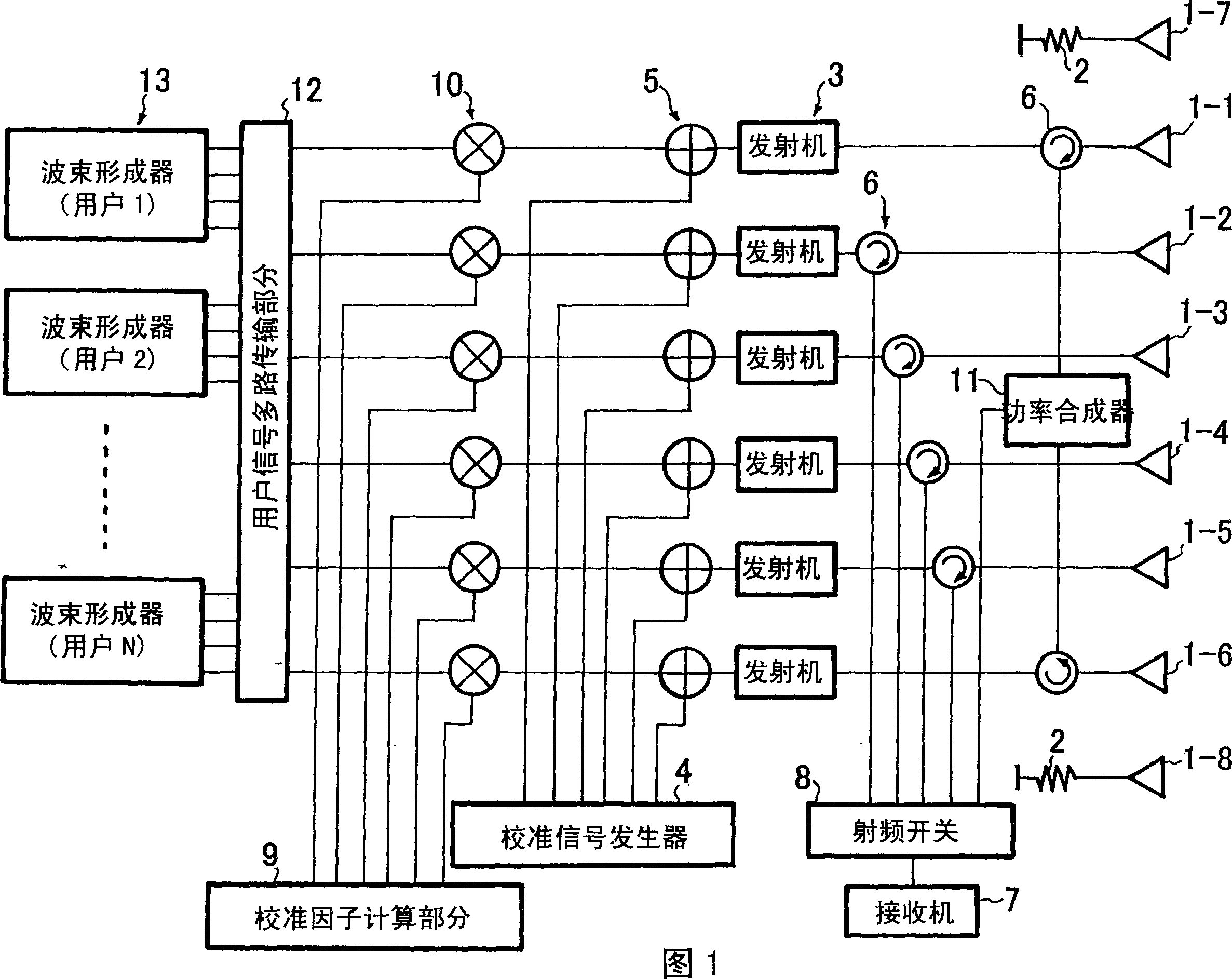
[0021] Fig. 1 is a structural block diagram of the array antenna calibration device of the present invention.

[0022] Referring to Fig. 1, the array antenna calibration device in the present embodiment comprises calibration signal generator 4, and it produces calibration signal, is used for making the phase and amplitude characteristic of antenna unit 1-1 to 1-6 radiation signal uniform, and these antenna units consist of Array antennas arranged linearly; adder 5, which adds the calibration signal to each user's multiplexed signal; circulator 6, which takes out electromagnetically coupled signals from adjacent antenna elements; receiver 7, which receives The signal taken out by the circulator 6; the radio frequency switch 8, which switches the input signal of the receiver 7; the calibration factor calculation part 9, which detects the calibration signal...


PUM


Abstract

An array antenna calibration apparatus simple in configuration and inexpensive while ensuring an accurate calibration of an array antenna is provided. This array antenna calibration apparatus includes supply means supplying original calibration signals to a plurality of antenna elements constituting an array antenna, the original calibration signals being orthogonal to one another among the antenna elements; a phase and amplitude characteristic calculation means calculating correlations between calibration signals, which are emitted from the antenna elements and received by the adjacent antenna elements, and the original calibration signals related to the received calibration signals; a relative calibration factor calculation means obtaining a relative calibration factor among all the antenna elements constituting the array antenna based on phase and amplitude characteristics of the respective antenna elements; and calibration means calibrating transmission signals to be supplied to the respective antenna elements based on the relative calibration factor.

Description

technical field [0001] The invention relates to an array antenna calibration arrangement for a radio base station. Background technique [0002] In order to form an accurate transmission beam with a digital beam former, it is necessary to make the phase characteristics and amplitude characteristics of signals radiated from each antenna element uniform. [0003] Fig. 5 is a block diagram of a conventional array antenna calibration device. The array antenna calibration device of conventional technology comprises beamformer 13 respectively to user 1 to N, user signal multiplexing part 12, multiplier 10, adder 5, transmitter 3, coupler 17, antenna 1, power combiner 18. Receiver 7, calibration factor calculation part 8 and calibration signal generator 4. [0004] Each beamformer 13 forms a beam having a certain directionality for each user. The user signal multiplexing section 12 multiplexes the beam for each of the users 1 to N, and outputs the user multiplexed signal for the...

Claims


Application Information

Patent Timeline
IPC IPC(8): H01Q3/26
CPCH01Q3/267H01Q3/26
Inventor 平部正司
Owner NEC CORP
Why Eureka
Try Eureka