

Digital directional relay
A relay and digital technology, which is applied in the field of digital directional relays, can solve the problems of unbalanced reverse-phase components, zero-phase components, low sensitivity of directional relays, and malfunctions, etc.
- Summary
- Abstract
- Description
- Claims
- Application Information
AI Technical Summary
Problems solved by technology
Method used
Image

Examples
no. 1 Embodiment
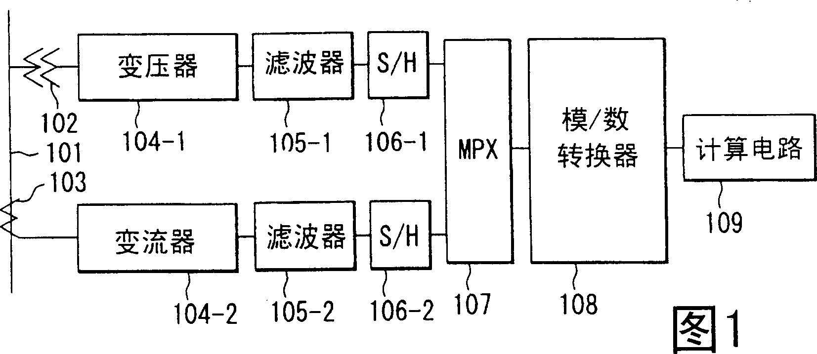
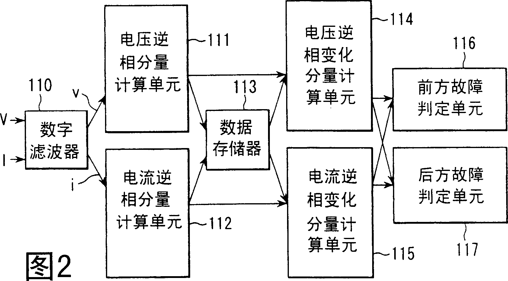
[0041] FIG. 2 is a block diagram of a first embodiment showing the functions of the calculation circuit 109 described above in the form of a plurality of calculation units. In Fig. 2, 110 is a digital filter. The digital filter 110 filters the input digital data V and I, and outputs v and I respectively to the calculation units 111 and 112 described later.
[0042] 111 is a voltage anti-phase component calculation unit. This voltage reverse-phase component calculating section 111 obtains the voltage reverse-phase component using, for example, the following equation (4).
[0043] 3V 2m =V Am +V B(m·8) +V C(m·4) (4)
[0044] In the formula, m is the sample value at the present moment, and a value is taken every 30° below, therefore, m·4 means the value before 120°.
[0045] 112 is a current anti-phase component calculation unit. The current reverse-phase component calculation unit 112 obtains the current reverse-phase component using, for example, the f...
no. 2 Embodiment
[0080] Figure 6 It is a block diagram of the second embodiment, which shows the functions of the calculation circuit 109 in the form of a plurality of calculation units.
[0081] The digital directional relay of the second embodiment obtains the reverse-phase unbalanced impedance from the reverse-phase-changing component current and the reverse-phase-changing component voltage, and determines the direction of the fault based on the value of the reverse-phase unbalanced impedance. In addition, various functions of the digital filter 110 to the current anti-phase change component calculation unit 115 are the same as those in the first embodiment shown in FIG. 2 , and their descriptions are omitted.
[0082] The impedance in the anti-phase unbalanced impedance can be used by I m (ΔV 2 / ΔI 2 ) to find out. The reverse phase unbalance component existing in the power system under normal conditions can be canceled by using the reverse phase unbalanced impedance obtained from the...
no. 3 Embodiment
[0099] Figure 8 It is a block diagram of the third embodiment, which shows the functions of the calculation circuit 109 in the form of a plurality of calculation units.
[0100] In the third embodiment, the digital filter 110 to the current reverse phase change component calculation unit 115 are the same as those in the first embodiment shown in FIG. 2 . And the absolute value calculation unit 120 and the inner product calculation unit 121 and Figure 6 The second embodiment shown is the same, and the description thereof is omitted.
[0101] Front failure determination means 131 determines the front failure based on the calculation results of absolute value calculation means 120 and inner product calculation means 121 and the establishment of determination formula (19) described later. Rear failure determination unit 132 determines a rear failure based on the calculation results of absolute value calculation unit 120 and inner product calculation unit 121 and the establishm...
PUM
 Abstract
Description
Claims
Application Information