Motor with earthing structure to reduce radio noise

A motor, elastic contact technology, applied in the field of motors, can solve problems such as increased cost of parts, loose electrical connections, loose connections between motor seat rings and end panels

Inactive Publication Date: 2003-08-27
DENSO CORP
View PDF0 Cites 5 Cited by
  • Summary
  • Abstract
  • Description
  • Claims
  • Application Information

AI Technical Summary

Problems solved by technology

[0003] Since the terminals are added, the cost of the entire part of the motor increases
In addition, when external forces are applied to the motor or vibrations are generated in the motor, the connection between th

Method used


Image

  • Motor with earthing structure to reduce radio noise
  • Motor with earthing structure to reduce radio noise
  • Motor with earthing structure to reduce radio noise

Examples


no. 1 approach

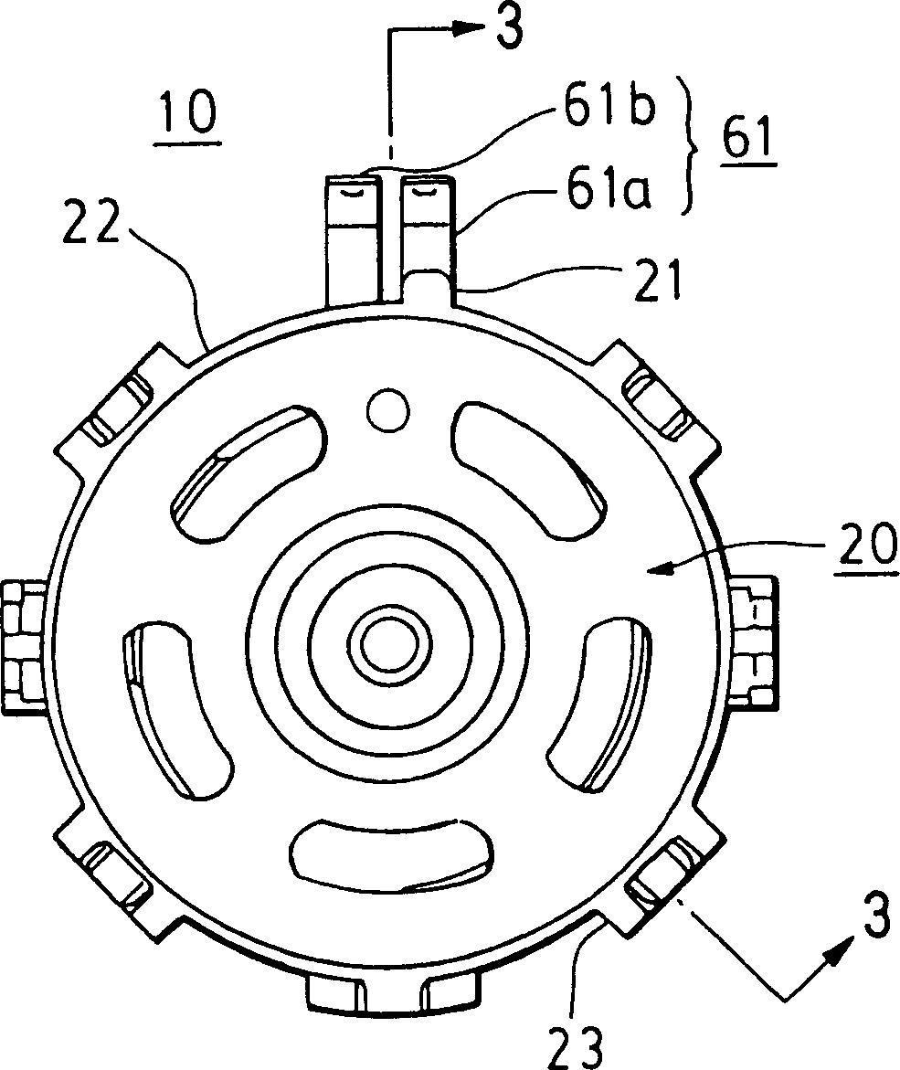
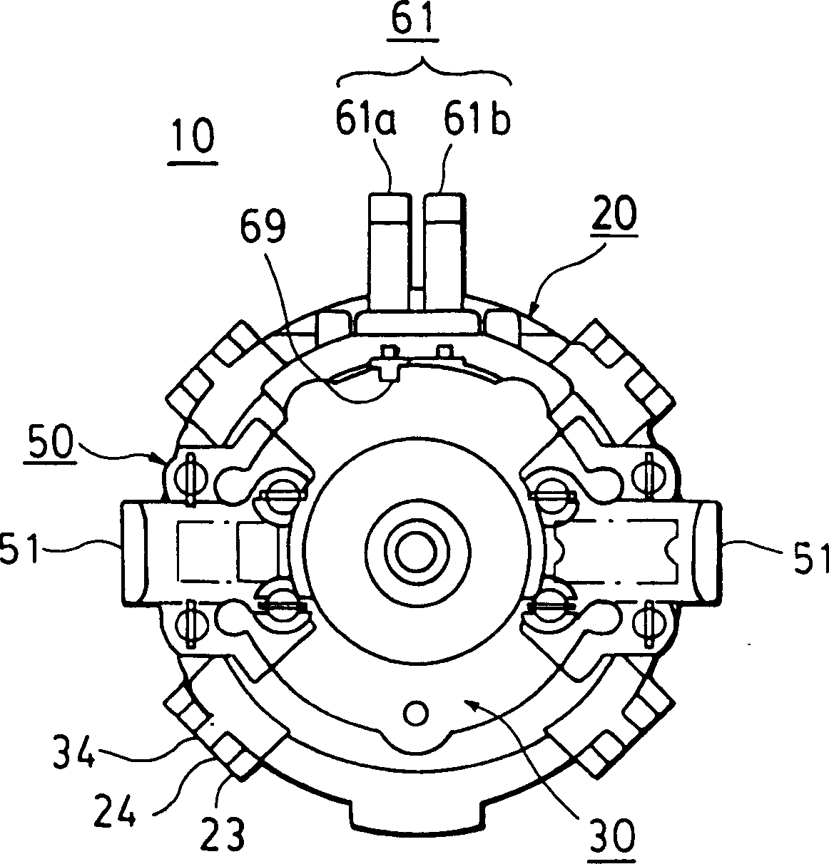
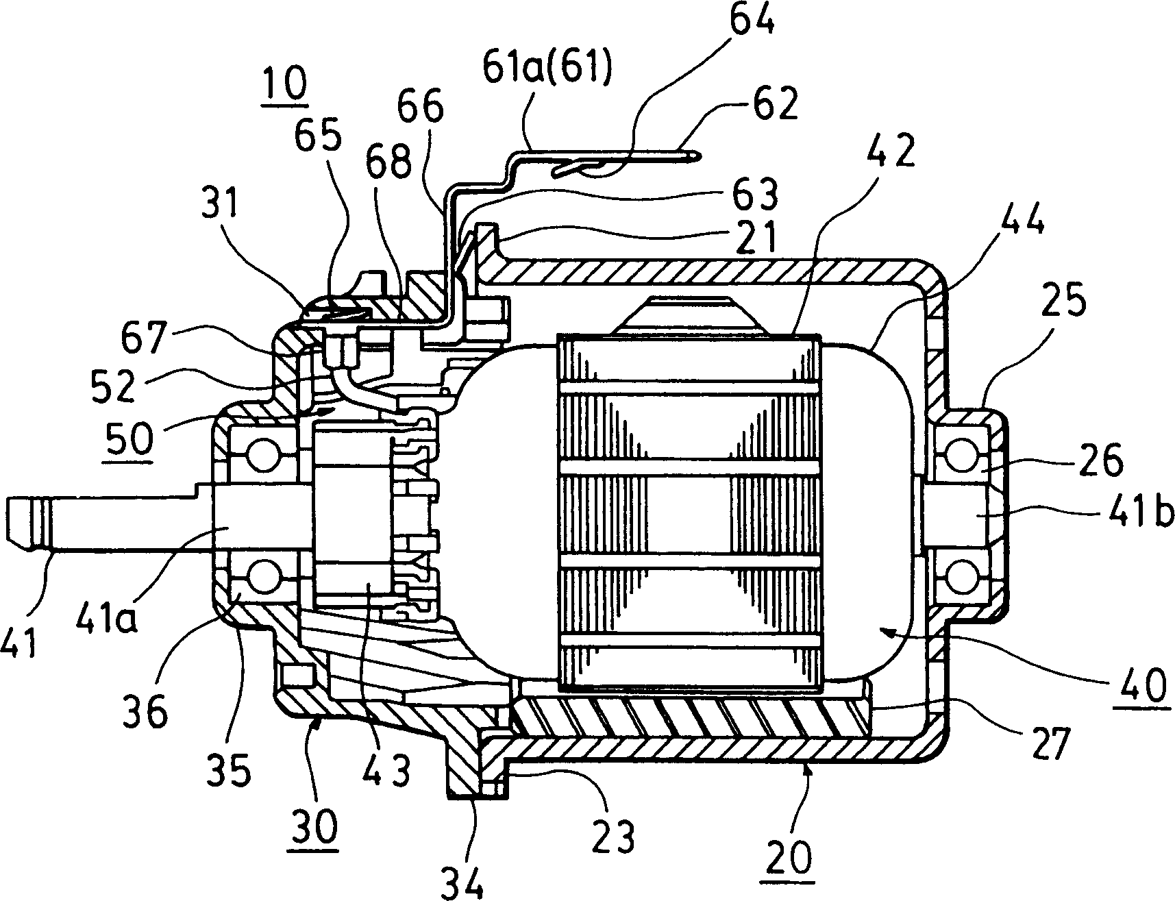
[0017] refer to Figures 1 to 3 , the motor 10 includes a motor race 20 , an end plate 30 , an armature 40 and a brush assembly 50 . The electric motor 10 is used for the blower on the vehicle. The motor race 20 is substantially formed in a cylindrical shape with one end closed for accommodating the armature 40 . The closed end of the motor race 20 has a concave bearing housing portion 25 . The bearing housing portion 25 houses a ball bearing 26 . A stator 27 consisting of magnets of substantially sector-shaped cross-section is disposed around the inner wall of the motor race 20 with a fixed gap in the circumferential direction.

[0018] A flange 22 is formed adjacent to the opening of the motor race 20 and along its edge, also referred to as an edge flange 22 . The ground flange 21 is formed at a predetermined portion of the edge flange 22 . The ground flange 21 also protrudes outward from the edge flange 22 and is electrically connected to the motor race 20 and the nega...

no. 2 approach

[0035] refer to Figure 6 , the edge flange 22 of the motor race 20 has a ground flange including a branch portion 121 . The contact portion 63 is bent in the branch portion 121 for grounding the motor race 20 . Due to this structure, the contact portion 63 is in close contact with the motor race 20 . Therefore, even when the contact between the motor race 20 and the end plate 30 becomes loose, the negative terminal 61 a is kept in contact with the motor race 20 . The radio noise occurring at the motor raceway can thus be continuously reduced. third embodiment

no. 3 approach

[0036] refer to Figure 7 , the edge flange 22 of the motor race 20 has a substantially disc-shaped ground flange 221 . At the center of the ground flange 221 , the boss 222 is parallel to the axial direction of the motor race 20 . In place of the contact portion 63, a contact portion 263 formed protrudes from the planar portion 66 of the negative terminal 61a. The contact portion 263 is bent toward the motor race 20, and its free end is bent so that the surface of its free end is substantially parallel to the surface of the ground flange 221.

[0037] There is a boss hole 264 in the center of the free end. The boss 222 is fitted into the boss hole 264 to couple the negative terminal 61 a with the motor race 20 . When the boss 222 is fitted into the boss hole 264, the motor race 20 is grounded. The entire surface of the bent free end of the contact portion 263 is pressed against the ground portion 221 . Therefore, even when the contact between the motor race 20 and the en...


PUM


Abstract

A motor includes a substantially cylinder-shaped motor yoke with an opening at one end, an end plate, and DC power input terminals. The end plate is positioned adjacent to the opening of the motor yoke, and the DC power input terminals are fixed to the end plate. The motor yoke has a grounding flange that protrudes from an outer periphery of the motor yoke adjacent to the opening. A negative terminal of the DC power input terminals has an elastic contact segment. The contact segment is pressed against the grounding flange to ground the motor yoke.

Description

technical field [0001] The present invention relates to a motor having a ground structure to reduce radio noise occurring at the motor race. Background technique [0002] In a direct current (DC) motor with brushes, the friction between the brushes and the commutator produces radio noise when the motor is operating. Radio noise occurring at the motor race can affect surrounding equipment. To reduce radio noise, the motor race needs to be grounded. Accordingly, such motors include terminals made of electrically conductive elastomeric material located between the motor race and an end plate disposed proximate to the opening of the motor race. To ground the motor race, connect the terminal to the negative terminal of the power supply or insert the negative terminal between the motor race and the end plate. [0003] Since the terminals are added, the cost of the whole part of the motor increases. In addition, when an external force is applied to the motor or vibrations are g...

Claims


Application Information

Patent Timeline
IPC IPC(8): H02K5/22H02K11/02
CPCH02K11/022Y10S439/926H02K11/0089H02K5/225H02K11/40H02K11/0141H02K11/02
Inventor 野田丈生铃木明彦
Owner DENSO CORP
Why Eureka
Try Eureka