
Device for guiding metal strip on gas cushion

A technology of metal strips and strips, applied in the direction of winding strips, transportation and packaging, furnace types, etc., can solve problems such as metal strips arching

Inactive Publication Date: 2003-09-03
彼得・埃布纳
View PDF1 Cites 8 Cited by
  • Summary
  • Abstract
  • Description
  • Claims
  • Application Information

AI Technical Summary

Problems solved by technology

Since the air cushion is used not only for the contactless guidance of the metal strip, but also for heat conduction, some thermal influences on the heat treatment of the metal strip must also be taken into account, which, among other things, can lead to consequences Yes, metal strips arch around a central longitudinal axis

Method used


Image

  • Device for guiding metal strip on gas cushion
  • Device for guiding metal strip on gas cushion

Examples


Embodiment Construction

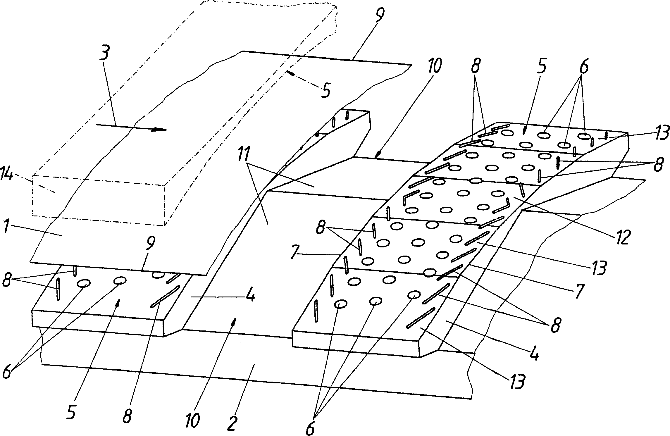
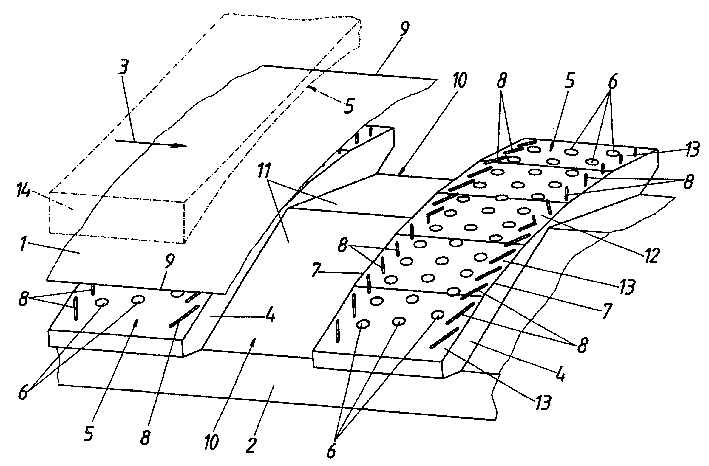
[0009] According to the illustrated embodiment, the device for guiding the metal strip 1 comprises a frame 2 carrying blowing boxes 4 arranged one behind the other in the longitudinal direction 3 of the strip and forming a nozzle area 5 . Said nozzle zone 5 extends transversely to the longitudinal direction 3 of the strip and comprises hole-type nozzles 6 which are distributed over the surface area of ​​the zone and through which gas (such as air) is blown to form holes against the metal strip 1. air cushion. Along the edge 7 of the nozzle area 5 extending transversely to the longitudinal direction 3 of the strip, there is a slot-shaped nozzle 8 which delimits the area of ​​the hole-shaped nozzle 6 and ensures with its gas jet the air cushion formed by the hole-shaped nozzle 6 . The air flow reflected on the metal strip 1 flows on the one hand between the two rows of slot-shaped nozzles in each nozzle area 5 against the longitudinal edge 9 of the metal strip 1 and on the othe...


PUM


Abstract

An apparatus is described for guiding a metal band (1) on a gas cushion with blowing boxes (4) which are disposed one after the other in the longitudinal direction (3) of the band and which comprise nozzle fields (5) which extend transversally to the longitudinal direction (3) of the band and comprise hole-type nozzles (6) distributed over the field surface area. In order to provide advantageous constructional conditions it is proposed that the nozzle fields (5) are provided with a convex basic shape through field sections (1, 3) which slope in at least one end section at either side transversally to the longitudinal direction of the band.

Description

technical field [0001] The invention relates to a device for guiding a metal strip on an air cushion, with blowing boxes arranged successively in the longitudinal direction of the strip and comprising a nozzle area extending transversely to the longitudinal direction of the strip, the nozzle area comprising distribution Orifice nozzles on the surface area of ​​the area. Background technique [0002] In order to be able to convey a metal strip floating on an air cushion in the longitudinal direction of the strip, it is known (DE 3026132 A) to provide blowers which are arranged in succession in the longitudinal direction of the strip and whose nozzle areas extend transversely to the longitudinal direction of the strip and Consists of orifice nozzles distributed over the surface area of ​​the region. The gas flowing through said hole-shaped nozzles against the metal strip forms a bearing air cushion secured by the gas flow from slot-shaped nozzles extending transversely to the...

Claims


Application Information

Patent Timeline
Patent Type & Authority Applications(China)
IPC IPC(8): B21C47/34B65H23/24C21D9/63
CPCC21D9/63B65H2406/112B21C47/3475B21C47/34B65H23/24
Inventor 彼得·埃布纳
Owner 彼得・埃布纳
Learn More