Radio base system, synchronization window control method, and synchronization window control program

A control method and base technology, applied in radio transmission systems, synchronous signal speed/phase control, diversity/multi-antenna systems, etc., and can solve problems such as interference between users, deterioration of call characteristics, and inability to identify and separate users.

Inactive Publication Date: 2003-09-03
SANYO ELECTRIC CO LTD
View PDF0 Cites 9 Cited by
  • Summary
  • Abstract
  • Description
  • Claims
  • Application Information

AI Technical Summary

Problems solved by technology

Therefore, the call characteristics for each user are deteriorated.
[0006] In addition, in the PHS, the reception signal from each mobile terminal device includes a reference signal section composed of a known bit sequence common to all users in each frame. If the reception signal from mobile terminal devices of multiple users If the synchronization positions of the signals are the same, the separated users cannot be identified due to the overlap of the reference signal intervals of the received signals, causing interference between users (so-called SWAP)

Method used


Image

  • Radio base system, synchronization window control method, and synchronization window control program
  • Radio base system, synchronization window control method, and synchronization window control program
  • Radio base system, synchronization window control method, and synchronization window control program

Examples


Embodiment approach 1

[0078] Figure 4 , is a flowchart showing the synchronization window control process according to Embodiment 1 of the present invention. This Embodiment 1 is meant to refer to image 3 A flowchart of the most basic processing explained.

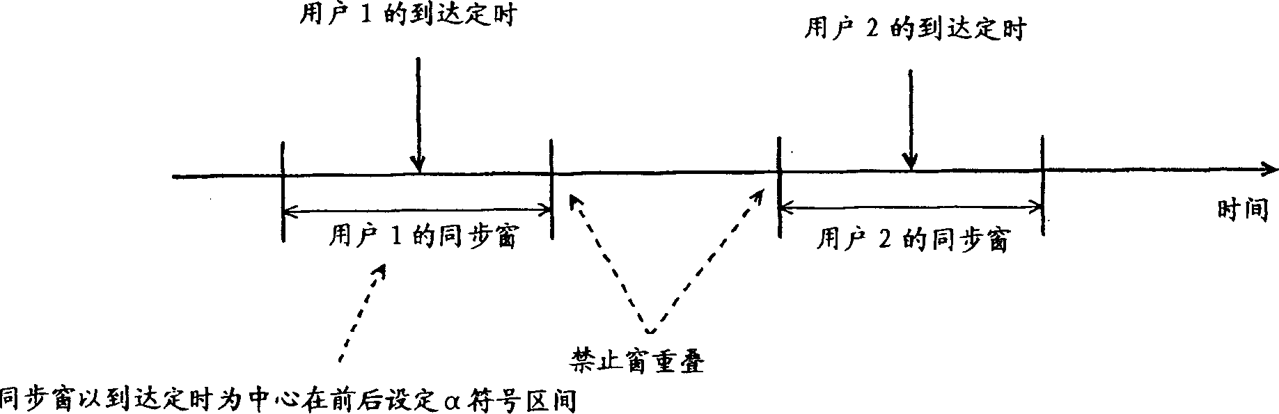
[0079] refer to Figure 4 First, in step S1, a synchronization window of the length of the preceding and following alpha symbols is set centering on the synchronization position estimated by a well-known method.

[0080] Next, in step S2, it is judged whether or not the interval between the synchronization windows of the multi-connected users is equal to or less than a predetermined threshold value 1 for preventing the synchronization windows from overlapping.

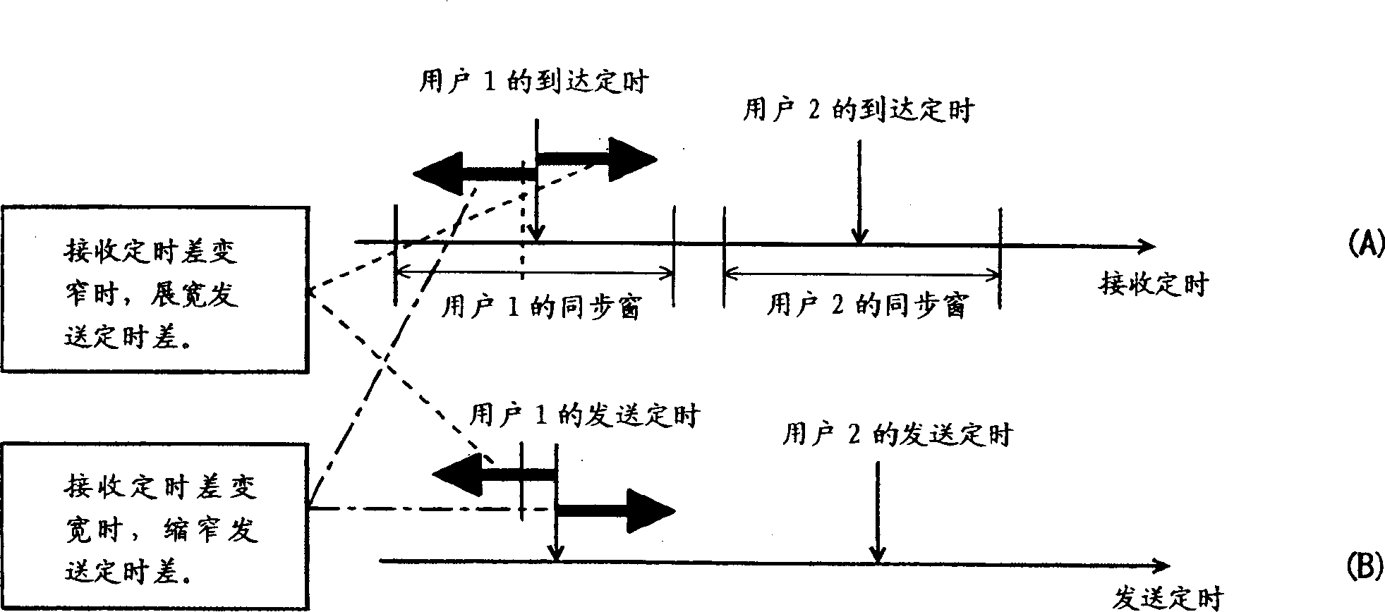
[0081] Then, if the interval is below threshold 1, proceed to step S4, as with respect to image 3 As described above, the process of widening the transmission timing difference between users is performed. In addition, the width by which the transmission timing is shifted once is s...

Embodiment approach 2

[0087] Figure 5 , is a flowchart showing the synchronization window control process according to Embodiment 2 of the present invention. The processing of steps S1 to S6 in Embodiment 2 is the same as Figure 4 The processing of steps S1 to S6 in Embodiment 1 is completely the same, and the description thereof will not be repeated here.

[0088] This second embodiment differs from the first embodiment in the following points. That is, when the reception timings of multiplexed users are rapidly approaching for some reason, it is too late to widen the transmission timing difference in step S4, and as a result, synchronization windows may overlap each other. If such a situation is left unattended, there is a danger of approaching and intersecting the synchronous positions, and therefore, some kind of countermeasure must be taken.

[0089] In the second embodiment, in step S7, it is judged whether such an overlap between synchronization windows has occurred after the control of...

Embodiment approach 3

[0093] Figure 6 , is a flowchart showing synchronization window control processing according to Embodiment 3 of the present invention. This Embodiment 3, except for the following point, is the same as Figure 5 Embodiment 2 is the same.

[0094] That is, as a countermeasure when it is judged in step S7 that an overlap between synchronization windows has occurred after the control of the transmission timing, in the third embodiment, in step S9, the synchronization window is removed from the synchronization window. Handling of parts that overlap each other. In other words, in the next reception frame, even if the reception timing reaches the portion where the synchronization windows overlap with each other, it is not regarded as a synchronization position.

[0095] Therefore, according to Embodiment 3, when the synchronization windows overlap even though the transmission timing is controlled, since the next reception timing in the overlapping portion of the synchronization w...


PUM


Abstract

For each of a plurality of users having multiple connection to a specific time slot a synchronization window of a predetermined temporal length having a center corresponding to a synchronization position is set to disallow a subsequent signal reception outside the widow. Furthermore timings of transmission for users are controlled to prevent synchronization windows from overlapping or being too distant from each other in the time slot. Thus, synchronization positions can be prevented from approaching each other or having an inverted time relationship therebetween. This process is provided by a DSP in software.

Description

technical field [0001] The present invention relates to a wireless base system, a synchronization window control method and a synchronization window control program, and more particularly relates to a wireless base system in which multiple mobile terminal devices can be connected in multiple ways in a mobile communication system, and in such a wireless base system A synchronization window control method and a synchronization window control program for correcting reception timing (synchronization position). Background technique [0002] In recent years, in mobile communication systems (for example, Personal Handyphone System: hereinafter abbreviated as PHS) that are rapidly and continuously developing, in order to improve the frequency utilization efficiency of radio waves, it has been proposed that by spatially dividing the same time slot of the same frequency, it is possible to use A PDMA method (Path Division Multiple Access) in which mobile terminal devices of multiple us...

Claims


Application Information

Patent Timeline
Patent Type & Authority Applications(China)
IPC IPC(8): H04B7/04H04B7/10H04B7/26H04J13/00H04J99/00H04L7/04H04W56/00H04W72/04
CPCH04B7/2662H04W56/005
Inventor 岩见昌志宫田健雄土居义晴
Owner SANYO ELECTRIC CO LTD
Why Eureka
Try Eureka