
Hardfacing alloy. methods and products

A hard and alloy technology, applied in the field of hard alloy surface hardening, can solve problems such as small mechanical failure, and achieve the effects of excellent wear resistance, low friction coefficient, and excellent metal-to-metal wear resistance

Inactive Publication Date: 2003-09-17
ATT TECH LTD
View PDF9 Cites 6 Cited by
  • Summary
  • Abstract
  • Description
  • Claims
  • Application Information

AI Technical Summary

Problems solved by technology

Although said materials have gained wide acceptance in the market, some users have expressed the need for an alloy for hardfacing of tool joints which has as little wear as possible and does not exhibit Weld cracks, to minimize the risk of mechanical failure performance

Method used


Image

  • Hardfacing alloy. methods and products
  • Hardfacing alloy. methods and products
  • Hardfacing alloy. methods and products

Examples


Embodiment 1

[0059] The preheating temperature is usually 100 to 400°C.

[0060] For tool joints of case-hardened AISI (American Iron and Steel Institute) 4137 steel, the preferred preheating temperature ranges are listed in Table 2 below.

[0061] Table 2

[0062] Tool joint O.D. preheating temperature

[0063] 3-1 / 8″~4-3 / 8″ 150~200°F (66~93°C)

[0064] 4-3 / 4″~5-1 / 4″ 200~250°F (93~121°C)

[0065] 5-1 / 2″~6-1 / 4″ 300~350°F (149~177°C)

[0066] 6-1 / 2″~6-3 / 4″ 350~400°F (177~204°C)

[0067] 7″~7-1 / 4″ 400~450°F (204~232°C)

[0068] 7-1 / 2″~7-3 / 4″ 450~500°F (232~260°C)

[0069] 8″~8-1 / 2″(nom.) 600~700°F(316~371℃)

[0070] 8″~8-1 / 2″(w / 5″id.) * 500~600°F (260~316°C)

[0071] * Tool joints of this size have much thinner wall thickness than standard tool joints.

Embodiment 2

[0073] For tool joints of case-hardened AISI 4145-HT steel, the preferred preheating temperature ranges are listed in Table 3 below.

[0074] table 3

[0075] Tool Joint / Drill Collar O.D. Preheat Temperature

[0076] Less than 4-3 / 4″ 150-200°F (66-93°C)

[0077] 4-3 / 4″~6-1 / 8″ 200~300°F (93~149°C)

[0078] 6-1 / 4″~7-1 / 4″ 300~400°F (149~204°C)

[0079] 7-1 / 2″~7-3 / 4″ 450~500°F (232~260°C)

[0080] 8″~8-1 / 2″(nom.) 600~700°F(316~371℃)

[0081] 8″~8-1 / 2″(w / 5″id.) * 500~600°F (260~316°C)

[0082] *A tool joint of this size has a much thinner wall thickness than a standard tool joint.

Embodiment 3

[0084] For tool joints of case-hardened AISI 1340-HT steel, the preferred preheating temperature range is listed in Table 4 below

[0085] Table 4

[0086] Tool joint O.D. preheating temperature

[0087] Less than 4-3 / 4″ 150-200°F (66-93°C)

[0088] 4-3 / 4″~6-1 / 8″ 200~300°F (93~149°C)

[0089] 6-1 / 4″~7-1 / 4″ 300~400°F (149~204°C)

[0090] 7-1 / 2″~7-3 / 4″ 450~500°F (232~260°C)

[0091] 8″~8-1 / 2″(nom.) 600~700°F(316~371℃)

[0092] 8″~8-1 / 2″(w / 5″id.) * 500~600°F (260~316°C)

[0093] *A tool joint of this size has a much thinner wall thickness than a standard tool joint.

[0094] Those of the preceding examples are representative preheat temperatures for those applications, used as examples of other preheat temperatures, depending on the size of the part to be hardfaced and the inherent properties of the matrix material, by simple Experiment OK.

[0095] The preheat temperature is preferably measured with a contact electronic pyrometer, although other temperature measure...


PUM

PropertyMeasurementUnit
hardnessaaaaaaaaaa

Abstract

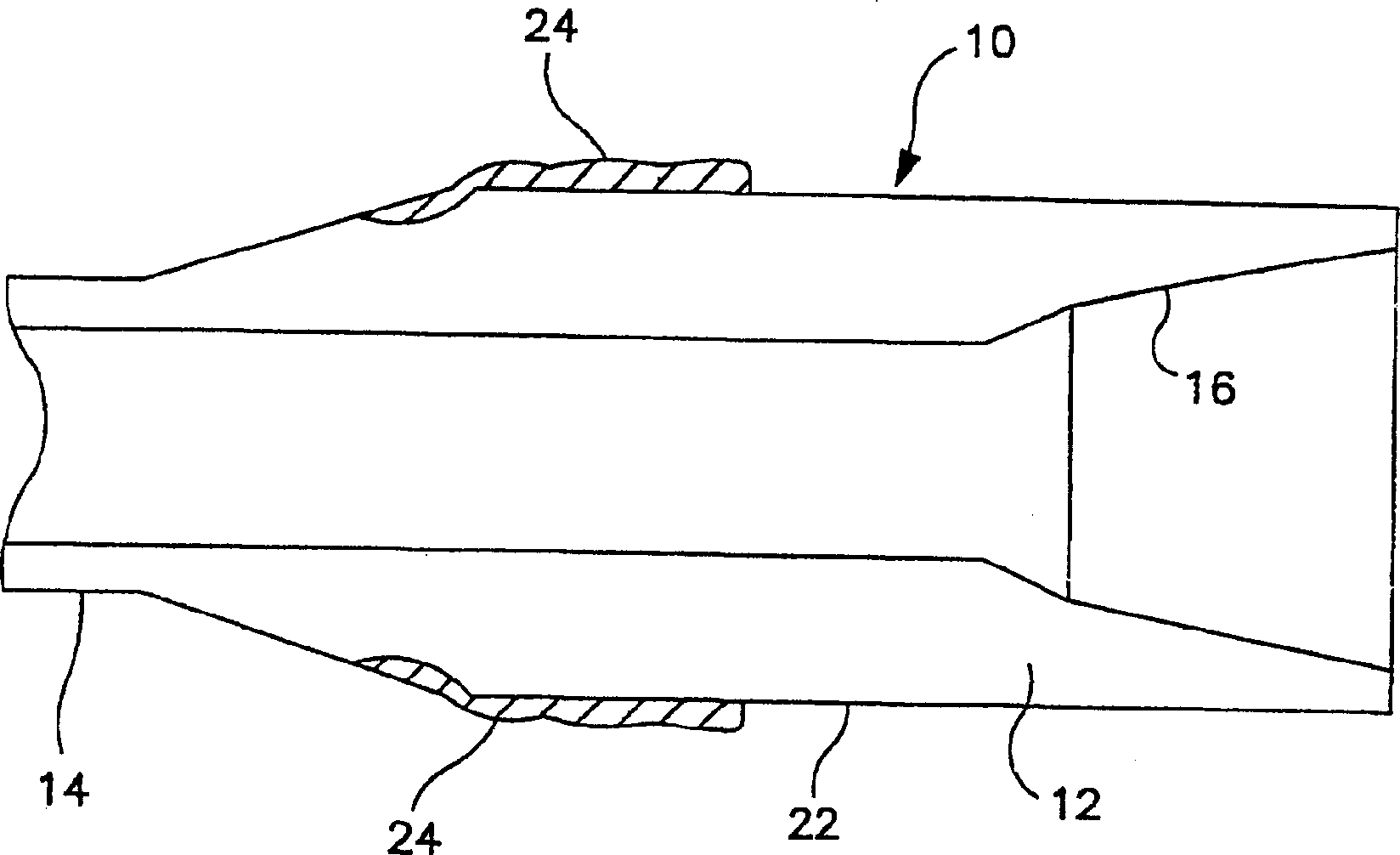
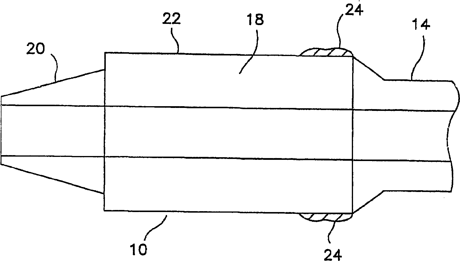
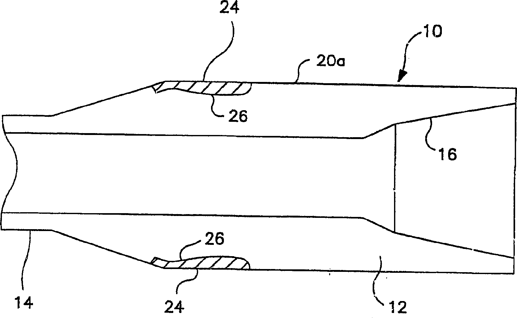
Disclosed is a hardfacing material capable of withstanding abrasion by siliceous formation particles, etc., weldable to industrial products such as drill joints and stabilizers for oil and gas well drilling, and other industrial products without cracks alloy. The alloy for surface hardening has a low coefficient of friction and high wear resistance after welding without machining, and in the tool joint and stabilizer, the wear resistance of the tool joint and the stabilizer and the resulting casing are obtained Optimal balance between wear and tear. Other embodiments of the invention include welding a hardfacing alloy (24) to the outer cylindrical surface (22) of the casing and pin components of a tool joint and to welding Tool joints on stabilizing ribs of stabilizers and other industrial products; methods of manufacturing said hardfacing alloys; methods of applying said hardfacing alloys on surfaces, including preheating and post-welding treatment conditions, In order to resist wear and tear.

Description

field of invention [0001] The present invention relates to the field of hardfacing alloys having high wear resistance which can be used to increase the service life of surfaces of industrial products subject to wear, such as tool joints, drill collars used in drill strings for oil and gas drilling and stabilizers and other industrial products subject to wear and tear. Background of the invention [0002] Since nearly 95% of the surface layer of the earth's crust is composed of abrasive, siliceous materials that can cause significant wear on tool joints and stabilizer surfaces and other industrial products' abrasive surfaces, it is very important for drilling such as drilling in the earth's crust to produce There have been serious problems with oil or gas tool joints and stabilizer life. [0003] Attempts have therefore been made to provide protective hardfacing alloys suitable for welding on tool joints. For a description of prior art hardfacing for tool joints see U.S. Pa...

Claims


Application Information

Patent Timeline
Patent Type & Authority Applications(China)
IPC IPC(8): E21B17/00B23K9/04B23K35/30C22C38/00C22C38/22
CPCB23K35/308C22C38/22Y10T428/12972
Inventor R·A·达门
Owner ATT TECH LTD
Learn More