A device for measuring wear of drill pipe connection section and casing

A drill pipe and casing technology, applied in the field of friction and wear measurement devices, can solve problems such as casing easy to rotate, point contact, collision, etc., and achieve the effect of avoiding multiple wear and good stability

Active Publication Date: 2022-06-07
SOUTHWEST PETROLEUM UNIV
View PDF20 Cites 0 Cited by
  • Summary
  • Abstract
  • Description
  • Claims
  • Application Information

AI Technical Summary

Problems solved by technology

At present, there is a device for evaluating the friction between the drill pipe and the casing, but it is difficult to simulate the linear friction between the actual connection section and the casing downhole. The experimental device and method of casing friction and wear, one end of the drill pipe is inserted into the casing, the casing is fixed, the drill pipe moves, and the force lever is used to push the drill pipe to move to make it fit and rub against the casing, in order to accurately simulate the uniformity of the pipe section Friction requires that the drill pipe should be translated in the direction of the inner wall of the casing during the bonding process, otherwise the outer wall of the drill pipe and the inner wall of the casing must not be parallel, resulting in a point contact between the two, resulting in local eccentric wear, which cannot simulate the actual wear of the pipe section However, as far as this device is concerned, the drill string is connected with the force lever, the spindle box, etc., and the supporting equipment is very complicated to move as a whole. Due to the lack of fixed facilities, the end vibrated greatly, which in turn caused the drill pipe and the sleeve to contact and rub against different parts along the circumference, and even collided. This is inconsistent with the linear friction in the actual formation, and the simulation results are reliable. The degree is also reduced
In addition, the Chinese patent application CN201420680047 discloses a device for measuring the sliding friction coefficient between the drill pipe and the casing. The casing is relatively movable, and the casing is used to move to compress the drill pipe. Its structure is relatively simple. However, the casing is positioned in the casing holder by using the rubber ring. When the drill string rotates, the casing is easy to rotate, resulting in The entire casing is worn in many places along the circumference, which does not match the wear of the fixed part of the casing under real conditions

Method used


Image

  • A device for measuring wear of drill pipe connection section and casing
  • A device for measuring wear of drill pipe connection section and casing
  • A device for measuring wear of drill pipe connection section and casing

Examples


Embodiment

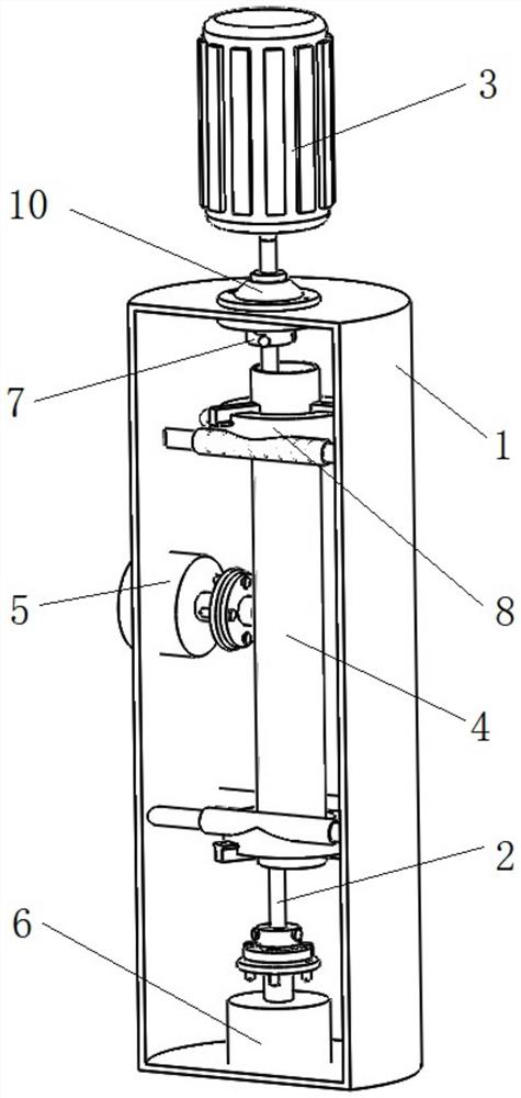
[0025] Please refer to figure 1 , figure 1 It is a sectional view of the overall structure of the present invention. A device for measuring the wear of drill pipe and casing, comprising a liquid storage tank 1, a drill pipe 2, a rotary motor 3, a sleeve 4, a horizontal force application mechanism 5 and an axial force application mechanism 6; the liquid storage tank 1 is used to carry The various components of the device and the storage drilling fluid; the rotary motor 3 is located outside the liquid storage tank 1, and is used to drive the drill pipe 2 to rotate; the drill pipe 2 is located in the liquid storage tank 1, and both ends extend out of the sleeve 4 and pass through the rotating parts. 7 is fixed in the liquid storage tank 1, specifically, the rotating part 7 located at the top of the drill pipe 2 is fixedly connected with the top of the liquid storage tank 1, and the rotating part 7 located at the bottom of the drill pipe 2 and the telescopic end of the axial forc...


PUM


Abstract

The invention discloses a device for measuring wear of a drill pipe and a casing, which comprises a bearing structure, a drill pipe, a rotating mechanism, a sleeve, and a horizontal force applying mechanism; the bearing structure is used to carry various parts of the device, and one end of the drill Through the sleeve, the rotating mechanism is used to drive the drill pipe to rotate; the two ends of the drill pipe are fixed on the bearing structure through the rotating parts; the sleeve is fixed on the bearing structure through the directional sliding mechanism, which defines the moving path, its sliding direction and The axis of the drill pipe is vertical; the telescopic end of the horizontal force-applying mechanism is in contact with the outer wall of the sleeve, and its telescopic direction is parallel to the sliding direction of the directional sliding mechanism, which is used to compress the sleeve and the drill pipe. The drill pipe of this device is relatively fixed, and the drill string moves and presses the drill pipe. The structure is relatively simple. At the same time, the drill string is guided to move by the directional sliding mechanism, which can ensure the linear contact between the drill pipe and the casing, and uniform force wear everywhere, and the casing The wear part is fixed, which can simulate the actual wear situation.

Description

technical field [0001] The invention relates to the technical field of friction and wear measuring devices, in particular to a device for measuring wear of drill pipes and casings. Background technique [0002] During the drilling process, the drill pipe rotates relative to the casing, the outer diameter of the pipe between the drill pipes is larger than that of the drill pipe, and the wear between the pipe and the casing is also the most serious. Therefore, in order to ensure the safety of the wellbore during the life period Evaluation of the degree of wear between casing and drill pipe joints. At present, there are devices for evaluating the friction between the drill pipe and the casing, but it is difficult to simulate the linear friction between the actual pipe section and the casing in the downhole. An experimental device and method for friction and wear of casing, one end of the drill pipe is inserted into the casing, the casing is fixed, the drill pipe moves, and the...

Claims


Application Information

Patent Timeline
Patent Type & Authority Patents(China)
IPC IPC(8): E21B47/00E21B41/00E21B17/04
CPCE21B47/00E21B41/00E21B17/04
Inventor 牟易升练章华林铁军张强于浩
Owner SOUTHWEST PETROLEUM UNIV
Why Eureka
Try Eureka