Debugging function built-in micro-computer

A technology for microcomputers and debugging functions, applied in general-purpose stored-program computers, computing, detecting faulty computer hardware, etc., and can solve problems such as inability to determine instructions or data.

Inactive Publication Date: 2003-09-24
SEIKO EPSON CORP
View PDF0 Cites 0 Cited by
  • Summary
  • Abstract
  • Description
  • Claims
  • Application Information

AI Technical Summary

Problems solved by technology

[0027] In addition, during the memory access by the CPU, when the memory access by the DMA is interrupted, there is a problem that the debugging tool 80 or the PC host computer 81 cannot determine which access i

Method used


Image

  • Debugging function built-in micro-computer
  • Debugging function built-in micro-computer
  • Debugging function built-in micro-computer

Examples


Embodiment Construction

[0042] The microcomputer with built-in debugging function of the present invention will be described in detail below in conjunction with the accompanying drawings.

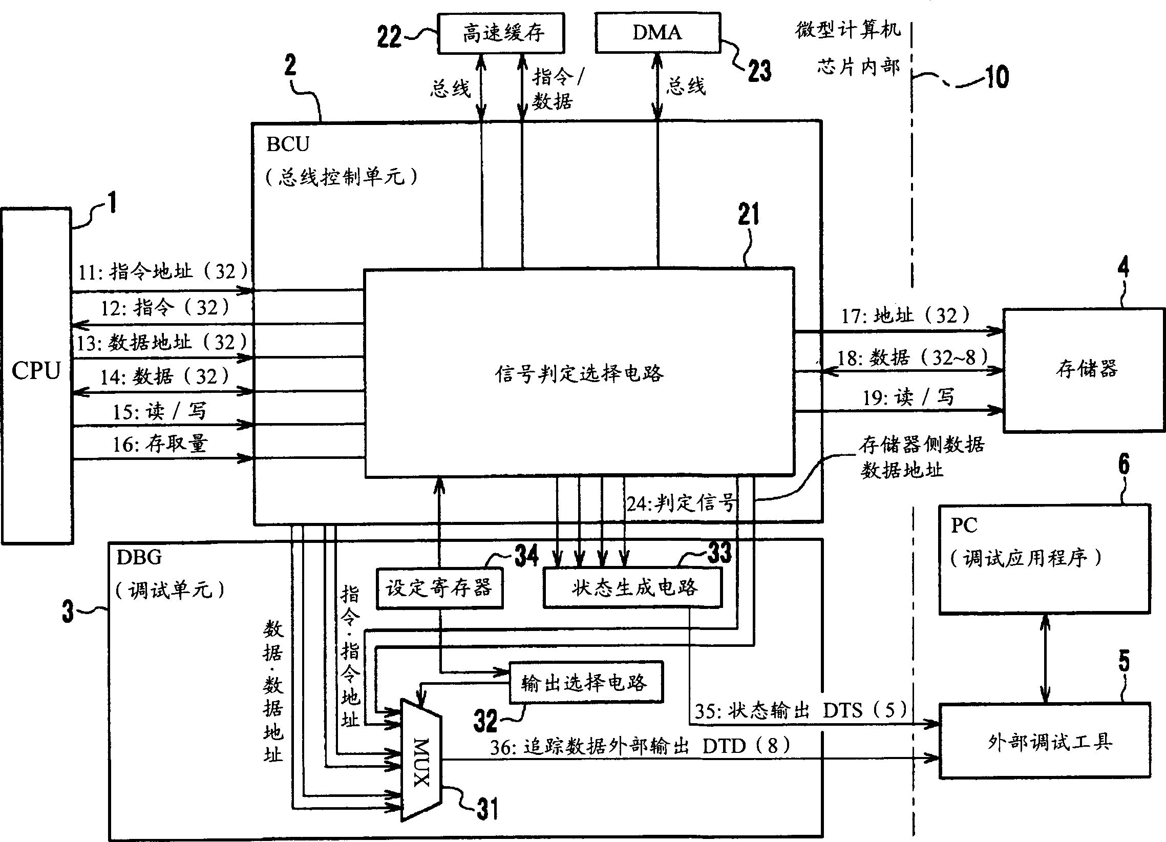
[0043] figure 1 It is a structural diagram of main parts of a debugging system using an embodiment of the microcomputer with a built-in debugging function of the present invention. exist figure 1 Among them, symbol 1 denotes CPU, symbol 2 denotes BCU (bus control unit), symbol 3 denotes DBG (debug unit), symbol 4 denotes memory, symbol 5 denotes an external debugging tool, and symbol 6 denotes a personal computer for debugging. In addition, reference numeral 22 indicates a cache memory, and reference numeral 23 indicates a DMA. CPU1, BCU2, DBG3, cache memory 22, and DMA23 are installed inside the microcomputer 10 chip. figure 1 The microcomputer equivalent of 10 Figure 10 The microcomputer 71 in CPU1 and BCU2 is equivalent to Figure 10 processor core 74, DBG3 is equivalent to Figure 10 The debug unit 7...


PUM


Abstract

The present invention provides a microcomputer with a built-in debugging function capable of compressing the output information by adopting an output signal with a bit width smaller than that of the command bus, creating an easy-to-analyze environment when tracing the contents of the command bus. In the debug function built-in microcomputer, the DBG (debugging unit) 3 outputs information 36 to be traced and status information 35 of information content to be traced from the status generation circuit 33 .

Description

technical field [0001] The invention relates to a microcomputer with a built-in debugging function, in particular to a microcomputer with a built-in debugging function having an improved bus tracing method. Background technique [0002] From the perspective of the purpose of finding program errors and supporting correction operations, the debugging function refers to stopping the execution of the program when tracing the program, reaching the specified line, or accessing the preset address or data, and notifying the outside while referring to it. Change the state of the memory or the content of the variable at that time. [0003] A debugging device (debugging tool) having such a debugging function has conventionally been called a path emulator. Figure 8 A block diagram of a debug system using such a path simulator is shown. Figure 8 The debugging system is composed of a user target system 50 and a debugging tool 55 for debugging the user target system 50 . Further, the us...

Claims


Application Information

Patent Timeline
IPC IPC(8): G06F11/28G06F11/22G06F11/36G06F15/78
CPCG06F11/364
Inventor 森垣利彦工藤真
Owner SEIKO EPSON CORP
Why Eureka
Try Eureka