Bimetallic valve push rod

A bimetal, push rod technology, applied in the direction of engine components, machines/engines, mechanical equipment, etc., can solve the problems affecting engine power and fuel consumption, affecting the opening and closing timing of intake and exhaust valves, and valve noise, etc. Machining, simplifying maintenance work, reducing the effect of valve noise

Inactive Publication Date: 2003-10-08
上海叠帆实业有限公司
View PDF0 Cites 4 Cited by
  • Summary
  • Abstract
  • Description
  • Claims
  • Application Information

AI Technical Summary

Problems solved by technology

However, this valve clearance is changed by the working temperature of the engine, so it affects the opening and closing time of the intake and exhaust valves, and finally affects the power and fuel consumption of the engine, and causes valve noise.

Method used


Image

  • Bimetallic valve push rod
  • Bimetallic valve push rod
  • Bimetallic valve push rod

Examples


Embodiment Construction

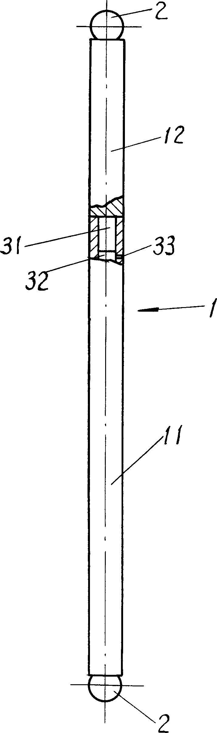
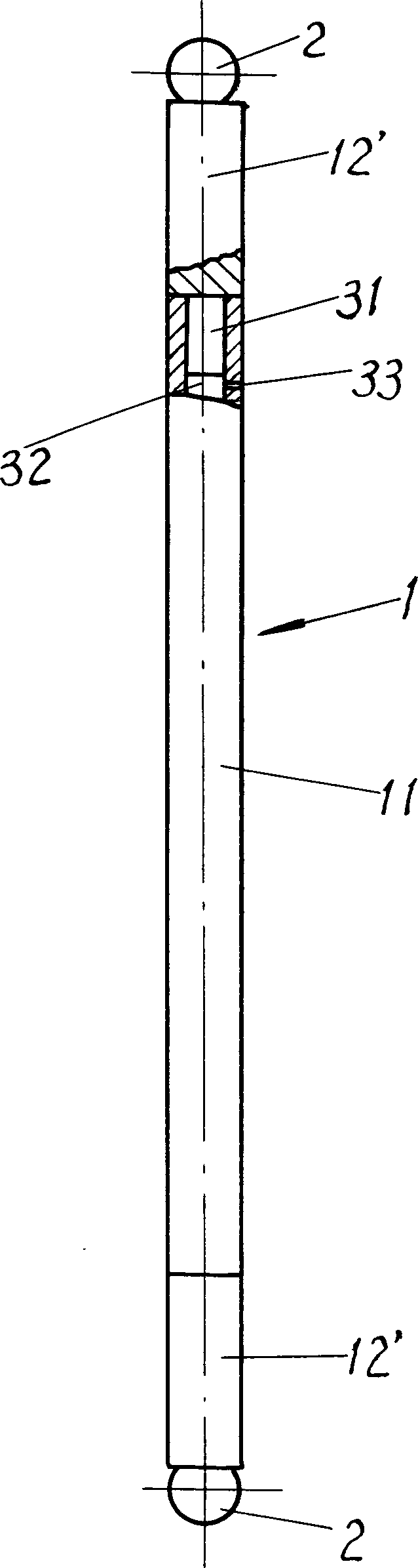
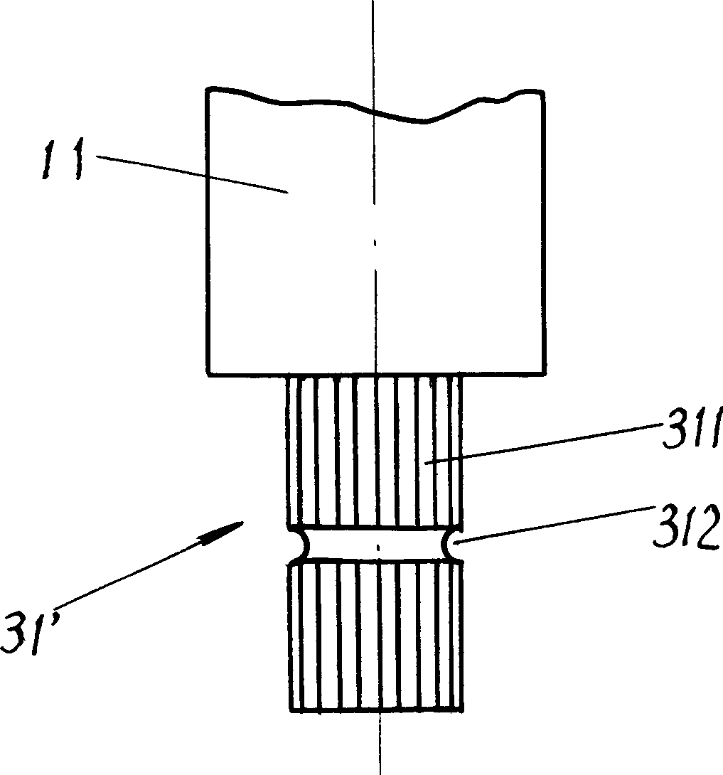
[0016] see figure 1 The shown engine valve push rod has a cylindrical shaft 1 and steel balls 2 arranged at both ends of the shaft 1 . The shaft 1 is composed of two shaft parts 11 and 12 . The shaft part 11 is larger than the overall expansion coefficient of the engine by the expansion coefficient (for example, is 20 * 10 -6 mm / 1℃), for example, the expansion coefficient is 23×10 -6 mm / 1℃ aluminum alloy. The shaft part 12 is then made of a material whose expansion coefficient is less than the overall expansion coefficient of the engine, for example, the expansion coefficient is 12×10 -6 mm / 1℃ carbon steel or 17.6×10 -6 mm / 1°C 1Cr18Ni9Ti alloy steel. By adjusting the respective length ratios of the shaft parts 11 and 12, the overall expansion coefficient of the shaft 1 is equal to or close to the overall expansion coefficient of the engine. The shaft part 11 and the shaft part 12 are connected by a mortise and tenon structure 3 . Usually, the bare body mortise 31 and th...


PUM


Abstract

A two-metal-material valve push rod characterizes in that the push rod is composed of two metal materials in different expansion coefficients with their rod poles connected and one of which expansioncoefficient is larger and the other is smaller than that of the motor, the length proportion of the said rod poles is adjusted to keep the expansion coefficient of the total push rod same or close tothat of the motor. This invention solves the problem of making expansion coefficient of the push rod same or close to that of the motor.

Description

Technical field: [0001] The present invention relates to engine parts, in particular to valve pushrods. Background technique: [0002] Most of the intake and exhaust mechanisms of four-stroke internal combustion engines use the valve push rod driven by the camshaft to open and close the intake and exhaust valves through the rocker arm. So far, the shaft of the valve push rod is made of a single metal. It was originally made of steel, and in recent years it is also made of aluminum alloy. Due to various reasons, the valve push rod is often inconsistent with the engine body and other related parts. . As we all know, metals expand when heated, and different materials have different coefficients of expansion. In order to prevent the phenomenon that the intake and exhaust valves of the engine are not closed tightly due to the difference in material expansion, the valve clearance is used to compensate. However, this valve clearance is changed by the engine operating temperature...

Claims


Application Information

Patent Timeline
Patent Type & Authority Applications(China)
IPC IPC(8): F01L1/14
Inventor 沈海星
Owner 上海叠帆实业有限公司
Why Eureka
Try Eureka