
Rotation impeller blade pump

A helical, medium pump technology, used in pumps, rotary piston pumps, rotary piston machines, etc., to achieve the effects of large pressure difference, low manufacturing and maintenance costs, and simple structure

Inactive Publication Date: 2003-10-08
彭德高
View PDF0 Cites 2 Cited by
  • Summary
  • Abstract
  • Description
  • Claims
  • Application Information

AI Technical Summary

Problems solved by technology

[0003] The technical problem to be solved by the present invention is to provide a high efficiency, low noise, large pressure difference, small wear, no pulsation, small volume, light weight, moderate manufacturing process requirements, and a wide range of application fields. rotary vane pump

Method used


Image

  • Rotation impeller blade pump
  • Rotation impeller blade pump
  • Rotation impeller blade pump

Examples


Embodiment Construction

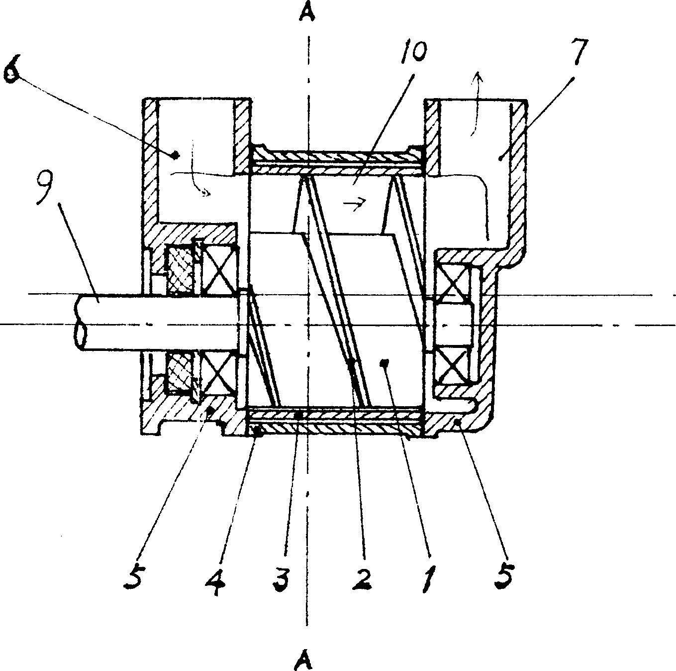
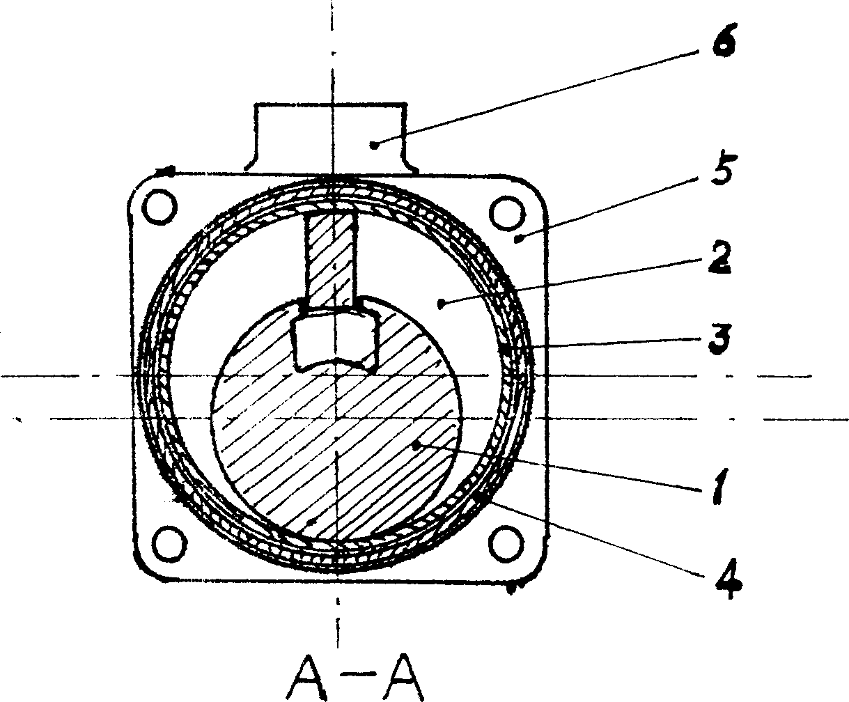
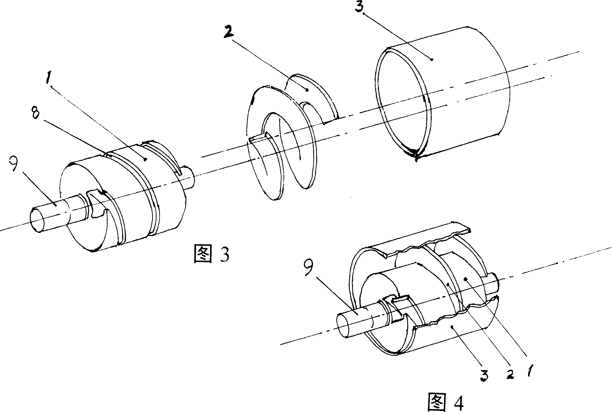
[0012] In the embodiment of the present invention, the rotor (1) is a cylindrical structure with helical grooves (8) processed on the axial surface for inserting the rotary blades (2), and there are shaft heads (9) at both ends as For positioning and power input. The rotary vane (2) is a helical structure like a compression spring with a flat cross-section and the same length as the rotor. The helical direction and pitch are consistent with the helical groove (8) of the rotor (1) and can be screwed into the rotor in the spiral groove (8). Its outer diameter and inner diameter are much larger than the outer diameter of the rotor (1) and the bottom diameter of the spiral groove (8). When the rotor (2) is combined with the rotor (1), it looks like a screw, but The rotary vane can slide eccentrically on the rotor (1), and when one side of the rotary vane is fully retracted into the helical groove (8) of the rotor, the other side slides out of the rotor like a crescent moon. The ...


PUM


Abstract

This invention relates to a rotary vane pump includes a rotor, a shell, medium inlet, medium pump outlet, in which, a screw slot is on the rotor, a screw rotary vane is inserted on the slot with follower slecve between the shell and the vane, the spindle nose of the rotor and the screw vane central line are of off-center structure. This invention has advantages of mechanicam pumps.

Description

technical field [0001] The invention belongs to the technical field of pumps and relates to a rotary vane pump. Background technique [0002] At present, all kinds of general-purpose mechanical pumps have advantages and disadvantages due to their own structure, and there are some shortcomings in application: 1. Centrifugal and axial flow pumps: low manufacturing process requirements, low wear, low noise, small pulsation, but high efficiency Low, small pressure difference. 2. Piston injection pumps: large pressure difference can be obtained, and the process requirements are moderate, but the efficiency is low, the wear is large, the noise is large, and the pulsation is large. 3. Screw and vane pumps: Although high efficiency, high pressure difference, and low noise can be obtained, the manufacturing process requirements are very high, and the contradiction between wear and sealing has not been effectively resolved. Contents of the invention [0003] The technical problem ...

Claims


Application Information

Patent Timeline
IPC IPC(8): F04C2/04
Inventor 彭德高
Owner 彭德高
Learn More