
Ray tester, its mfg. method and ray CT appts.

A detector and ray technology, applied in the field of ray detectors, can solve the problems of attenuation of light reflectivity, reduction of output current, reduction of output current, etc.

Inactive Publication Date: 2003-10-08
HITACHI METALS LTD
View PDF0 Cites 11 Cited by
  • Summary
  • Abstract
  • Description
  • Claims
  • Application Information

AI Technical Summary

Problems solved by technology

[0007] However, the ray detectors in use now gradually reduce the output current due to being irradiated, and for a cumulative 500,000 roentgens, the output current is reduced by nearly 10% compared to the initial output
Because the output current is reduced by 10% or more, the resolution of the X-ray CT device is attenuated, so a good CT image cannot be obtained, and the X-ray detector needs to be replaced, which generates a lot of cost
[0008] Factors that lead to the attenuation of the radiation detector output include: semiconductor photodetection element loss and scintillator itself luminous intensity attenuation; however, it has been found that the most important factor is the light reflection caused by radiation in the light reflective material formed on the surface of the scintillator Significant attenuation of rate

Method used


Image

  • Ray tester, its mfg. method and ray CT appts.
  • Ray tester, its mfg. method and ray CT appts.
  • Ray tester, its mfg. method and ray CT appts.

Examples


Embodiment Construction

[0050] Detailed Description of Preferred Embodiments

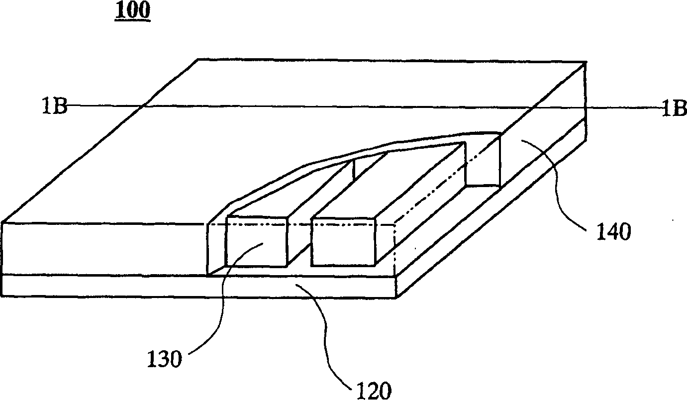
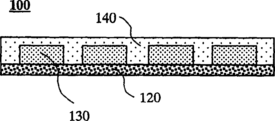
[0051] Fig. 1 has shown the perspective view of the radiation detector according to the present invention, for the convenience of explanation, the reflective material part is cut off, Figure 1B is along Figure 1A The sectional view of the ray detector of line 1B-1B in. To reveal the internal structure, Figure 1A The double-dashed line part stripped off the light reflective material. In the radiation detector 100, a plurality of rectangular planar scintillators 130 are arranged in a row at regular intervals on the semiconductor photodetection element array 120, which converts light into electricity. In the figure, the semiconductor photodetection element array 120 is described as a single object, but its interior is actually composed of a plurality of photoelectric elements facing multiple scintillators respectively. In FIG. 1 , for ease of illustration, the number of scintillators is assumed to be 4, but 8-24 scinti...


PUM

PropertyMeasurementUnit
Average particle sizeaaaaaaaaaa

Abstract

Due to the radiation, the resin in the radiograph undergoes a change in properties. Such property changes include light reflectance and light transmittance attenuation of the resin. One consequence of the change in resin properties is a reduction in the output current of the detector and affects the operating life of the detector. Provided is a radiation detector and a CT device, which have a small attenuation of the output current of the detector even under a large amount of radiation, and have a long working life. A cured mixture of rutile-type titanium oxide powder and polyester resin was used for the light reflective material covering the scintillator. Also, polyester resin is used to bond the scintillator and the semiconductor photodetection element.

Description

technical field [0001] The present invention relates to a radiation detector, in particular to a radiation detector used in computed tomography (CT) equipment using radiation such as X-rays, gamma-rays, and the like. Background technique [0002] Figure 8 A schematic diagram showing a radiation CT apparatus using a radiation detector. The subject 51 is placed at the center of the CT apparatus. A radiation source 52 (such as an X-ray tube) is arranged on the outer peripheral side of the gantry 50 that rotates around the subject 51, and a plurality of radiation detectors 8 are arranged at positions opposite to the radiation source 52, and the subject 51 is between them. between. The radiation 53 diverging from the radiation source 52 in a fan shape passes through the subject 51 , is absorbed by various parts of the subject 51 at the same time, and reaches the radiation detector 8 . Each part of the subject 51 absorbs the radiation 53 differently, so the intensity of the ra...

Claims


Application Information

Patent Timeline
IPC IPC(8): G01T1/20G01T1/24G11B5/84
CPCG01T1/2002
Inventor 角田健一松井进
Owner HITACHI METALS LTD
Learn More