
Current attenuation mode control circuit of motor drive chip

A motor drive chip, current attenuation technology, applied in the direction of motor generator control, control system, electrical components, etc., can solve the problems of noise, motor weakness, loss of step and so on

Active Publication Date: 2014-04-02
JIAXING ZHONGRUN MICROELECTRONICS
View PDF4 Cites 9 Cited by
  • Summary
  • Abstract
  • Description
  • Claims
  • Application Information

AI Technical Summary

Problems solved by technology

Therefore, the stepping motor drive circuit needs to detect the running speed of the motor in real time. Otherwise, when the running speed of the motor is reduced from high speed to low speed, the fast decay mode will still be used, which will cause the motor to be weak, and in serious cases, the phenomenon of step loss and out of step will occur; After the running speed of the motor is increased from low speed to high speed, if the slow decay mode is still used, the motor will vibrate violently and emit a lot of noise

Method used


Image

  • Current attenuation mode control circuit of motor drive chip
  • Current attenuation mode control circuit of motor drive chip

Examples


Embodiment Construction

[0027]Below in conjunction with accompanying drawing, the embodiment of the present invention is described in detail: present embodiment implements under the premise of the technical scheme of the present invention, has provided detailed implementation and specific operation process, but protection scope of the present invention is not limited to the following the embodiment.

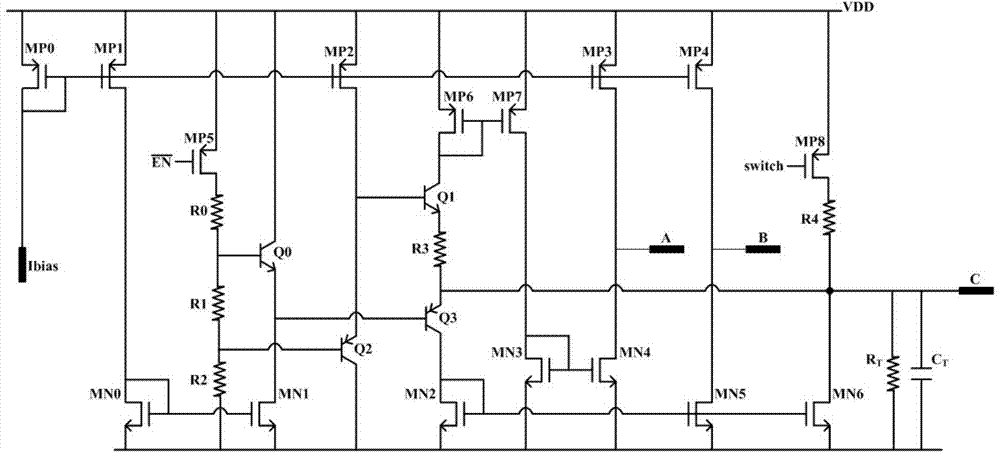
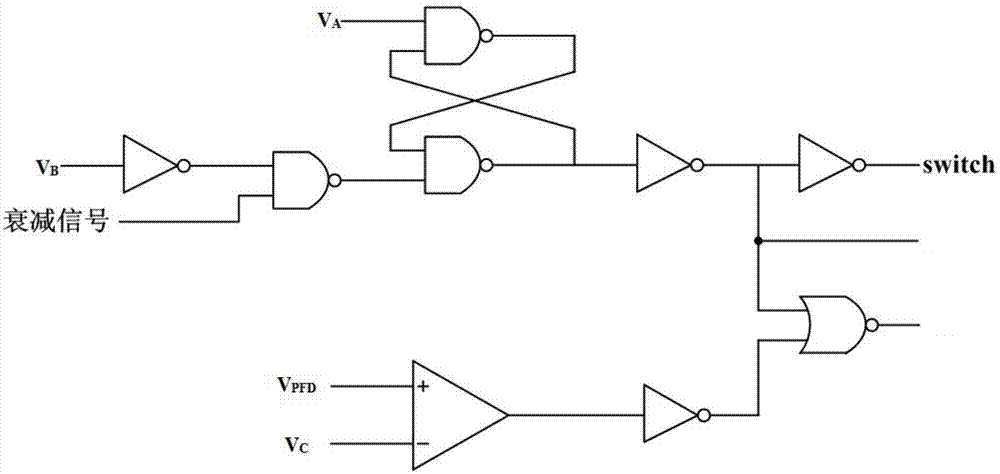
[0028] A current decay mode detection circuit of a motor drive chip of the present invention includes three parts: a current decay time control circuit, an external parallel circuit and a digital logic control circuit, wherein the current decay time control circuit and the external parallel circuit are specifically as follows figure 1 As shown, the digital logic control circuit is specifically as figure 2 shown.

[0029] Such as figure 1 As shown, the current decay time control circuit includes several PMOS transistors, several NMOS transistors, a core circuit and a current mirror structure. enable ...


PUM

PropertyMeasurementUnit
Resistanceaaaaaaaaaa
Capacitanceaaaaaaaaaa

Abstract

A current attenuation mode detection circuit of a motor drive chip comprises a current attenuation time control circuit, an external parallel connection circuit and a digital logic control circuit, wherein the current attenuation time control circuit comprises a plurality of NMOS (N-channel Metal Oxide Semiconductor) transistors, a plurality of PMOS (P-channel Metal Oxide Semiconductor) transistors, a core circuit and a current mirror structure, wherein the external parallel connection circuit includes a capacitor CT and a resistor RT, and is connected with the current attenuation time control circuit; the digital logic control circuit includes a comparer, a latch, and a logic gate circuit; the input signal of the digital logic control circuit is the output signals of both the current attenuation time control circuit and the external parallel connection circuit; the output switch signal of the digital logic control circuit is still fed back to the current attenuation time control circuit; the current attenuation time depends on the CT and the RT; the fast attenuation time and the slow attenuation time are controlled by the current attenuation time control circuit and the digital logic control circuit together. The current attenuation mode detection circuit provided by the invention realizes switching in intelligent control between current rise process and current attenuation process according to motor operating speed.

Description

technical field [0001] The invention relates to the current control of the motor drive chip, in particular to the control of the current decay mode of the motor drive chip. Background technique [0002] A stepper motor is an open-loop control element stepper motor that converts electrical pulse signals into angular displacement or linear displacement. When the stepper driver receives the pulse signal, it drives the stepper motor to rotate a fixed angle in the set direction, that is, the step angle, and the rotation of the stepper motor runs step by step at a fixed angle. The stepper motor can control the angular displacement by controlling the number of pulses to achieve accurate positioning. At the same time, the speed and acceleration of the motor can be controlled by controlling the pulse frequency to achieve the purpose of speed regulation. [0003] At present, the stepper motor basically uses the current subdivision method to subdivide the step angle. The current poin...

Claims


Application Information

Patent Timeline
IPC IPC(8): H02P8/12
Inventor 湛衍黄武康杨志飞代军姚远王良坤陈路鹏夏存宝万巧玲
Owner JIAXING ZHONGRUN MICROELECTRONICS
Learn More