Centerless grinding apparatus and centerless grinding process

一种无心磨削、磨削的技术,应用在磨削/抛光设备、为磨削工件旋转面设计的机床、金属加工设备等方向

Inactive Publication Date: 2003-10-15
NSK LTD
View PDF3 Cites 22 Cited by
  • Summary
  • Abstract
  • Description
  • Claims
  • Application Information

AI Technical Summary

Problems solved by technology

[0009] According to the equipment disclosed in JP-A-6-339842, although the inner diameter surface and end surface of the workpiece can be processed by one-time clamping, it is impossible to simultaneously grind the outer diameter surface and end surface of the workpiece due to the interference between the chuck and the grinding wheel

Method used


Image

  • Centerless grinding apparatus and centerless grinding process
  • Centerless grinding apparatus and centerless grinding process
  • Centerless grinding apparatus and centerless grinding process

Examples


Embodiment Construction

[0034] Embodiments of the present invention will be described with reference to the drawings.

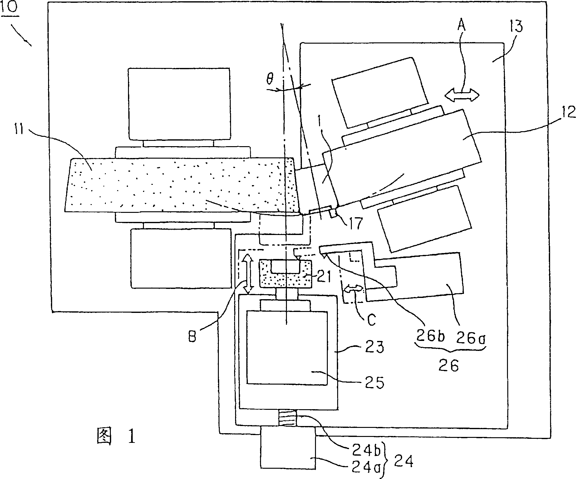
[0035] Fig. 1 is a schematic plan view of a centerless grinding apparatus 10 according to a first embodiment of the present invention. The centerless grinding apparatus 10 is suitable for grinding a workpiece such as a tapered roller 1 or the like. The first grinding mechanism for grinding the outer diameter surface of the workpiece 1 includes an outer diameter surface grinding wheel 11 formed in a disk shape, an adjustment wheel 12, and a device for respectively moving the adjustment wheel 12 closer to the outer diameter surface grinding wheel 11 and from the outer diameter surface. Outer diameter surface cutting table 13 separated from surface grinding wheel 12, supporting blade for supporting workpiece 1 from the lower side of the workpiece (supporting workpiece 1 from the rear of the figure), and dressing device for outer diameter surface grinding wheel 11 and adjustment wheel 1...


PUM


Abstract

A centerless grinding apparatus ( 10 ) includes an outer diameter surface grinding wheel ( 11 ) for grinding the outer diameter surface of a work ( 1 ) of a substantially cylindrical shape, a regulating wheel ( 12 ) for supporting the outer diameter surface of the work ( 1 ) in conjunction with the outer diameter surface grinding wheel ( 11 ) and an end surface grinding wheel ( 21 ) for grinding the end surface of the work ( 1 ). The end surface grinding wheel ( 21 ) grinds the end surface of the work ( 1 ) while the outer diameter surface grinding wheel ( 11 ) grinds the outer diameter surface of the work ( 1 ) in a state that the work ( 1 ) is disposed between the outer diameter surface grinding wheel ( 11 ) and the regulating wheel ( 12 ).

Description

technical field [0001] The present invention relates to an in-feed type centerless grinding apparatus. Background technique [0002] For example, centerless grinding equipment for manufacturing rollers of rolling bearings is classified into an infeed type, a through-feed type, and a tangential-feed type. [0003] According to the infeed type, the workpiece is ground into a predetermined shape by radially feeding the grinding wheel or the adjusting wheel in a state where it is set in the grinding space between the rotating grinding wheel and the rotating adjusting wheel. [0004] Conventionally, the outer diameter surface and the end surface of the workpiece are respectively ground by different grinding equipment in such a manner that the workpiece subjected to heat treatment is first ground on its outer diameter surface and then ground at its end surface. Furthermore, for workpieces requiring high precision, in order to obtain sufficient accuracy of the end face serving as ...

Claims


Application Information

Patent Timeline
Patent Type & Authority Applications(China)
IPC IPC(8): B24B5/18B24B5/01B24B5/22B24B5/24B24B7/16B24B27/00B24B53/047
CPCB24B5/24B24B7/16B24B5/22B24B27/0076B24B5/01
Inventor 鎌村有宏岩浪博之
Owner NSK LTD
Why Eureka
Try Eureka