
Cross flow fan

A cross-flow fan and fan technology, which is applied to the components of pumping devices for elastic fluids, non-variable-capacity pumps, machines/engines, etc., can solve the problems of slow air flow, stall, blade damage, etc. Efficiency improvement, discharge prevention, stall prevention effect

Inactive Publication Date: 2003-10-29
LG ELECTRONICS (TIANJIN) APPLIANCES CO LTD
View PDF0 Cites 3 Cited by
  • Summary
  • Abstract
  • Description
  • Claims
  • Application Information

AI Technical Summary

Problems solved by technology

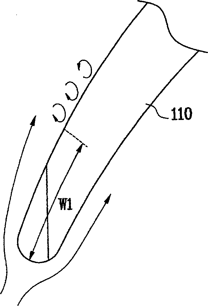
[0010] This kind of stall phenomenon is in the working state other than the design point, that is, when the air flow speed is slow, on the contrary, when the rotation speed of the blade is fast, the stall phenomenon often occurs, which eventually reduces the efficiency, and even the blade will be damaged

Method used


Image

  • Cross flow fan
  • Cross flow fan
  • Cross flow fan

Examples


Embodiment Construction

[0027] Below in conjunction with accompanying drawing and specific embodiment the present invention is described in further detail:

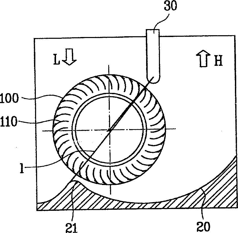
[0028] Figure 2a It is a sectional view of the cross-flow fan structure of the present invention. Figure 2b yes Figure 2a An enlarged view of air flow over the blades of a cross-flow fan.

[0029] Such as Figure 2a As shown, the structure of the cross-flow fan is as follows: the impeller 100 that generates air flow is combined with the shaft of the motor; the rear guide rail 20 bent according to a specific curvature is arranged behind the impeller housing to form a discharge flow path for the inhaled air; the stabilizer 30 is along the The axial direction is set on one side of the impeller housing to stabilize the vortex generated in the impeller inner area, and together with the gap part of the rear guide rail, forms a boundary that divides the high-pressure part H and the low-pressure part L.

[0030] The impeller 100 is composed of a ...


PUM


Abstract

A cross-flow fan without stall phenomenon is composed of serially connected multiple fans, curved back guide to form exhaust channel, axially arranged stabilizer to form an interface between high andlow pressures and eddy generator arranged to near the front end of vanes for converting the in-coming air to eddy current with high kinetic energy. Each fan has many curved vanes.

Description

technical field [0001] The invention relates to a fan for an air conditioner, in particular to a cross-flow fan Background technique [0002] Generally, a blower is installed on an air conditioner or a refrigeration device, etc., to forcibly suck in or exhaust outside air or cool air. According to the discharge pressure, this kind of blower is divided into low-pressure fan and high-pressure blower; according to the blade, it is divided into centrifugal blower, axial flow blower, cross flow blower, etc. Among them, the cross-flow fan is a kind of cross-flow blower. There is no suction flow in the axial direction, but the suction and discharge of air are generated in the plane from the impeller axis to the plane. Cross-flow fans are generally beneficial to produce high positive pressure and large air volume, and are widely used in air conditioners, especially window air conditioners and ceiling air conditioners, due to the uniform flow in the axial direction. [0003] The st...

Claims


Application Information

Patent Timeline
Patent Type & Authority Applications(China)
IPC IPC(8): F04D29/44
Inventor 严允燮金正勳具廷楦黄性万
Owner LG ELECTRONICS (TIANJIN) APPLIANCES CO LTD
Learn More