Apparatus for separating plastic chips

A screening device and technology for plastics, used in plastic recycling, mechanical material recycling, electrostatic effect separation, etc., can solve problems such as inability to screen with high purity and high recovery rate

Inactive Publication Date: 2003-11-05
HITACHI ZOSEN CORP
View PDF0 Cites 16 Cited by
  • Summary
  • Abstract
  • Description
  • Claims
  • Application Information

AI Technical Summary

Problems solved by technology

Thereby, when mixing in the plastic sheet the order bit of charging sequence close, those kind of plastic sheet that the difference of charge amount is very little, in above-mentioned existing plastic screening device, just exist can not be with the high rate of more than 99%. Purity and high recovery for screening issues

Method used


Image

  • Apparatus for separating plastic chips
  • Apparatus for separating plastic chips
  • Apparatus for separating plastic chips

Examples


Embodiment Construction

[0027] In order to illustrate the present invention in more detail, we illustrate according to accompanying drawing.

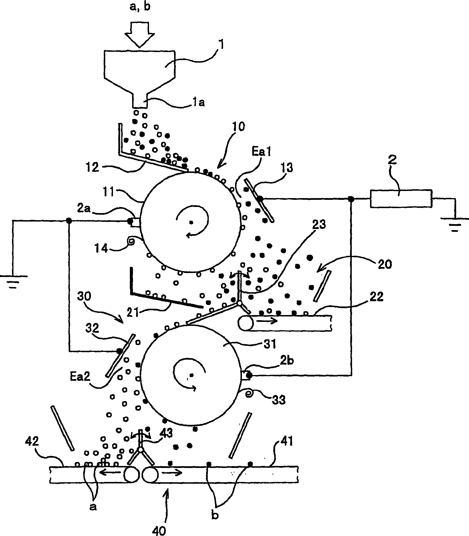
[0028] First, we refer to figure 1 and figure 2 The first embodiment of the plastic screening device related to the present invention will be described.

[0029] This type of plastic screening device has a part that mixes at least two or more different types (materials) of plastic chips (such as shredded plastic waste for screening) a, b in a state of mixing, and makes the different types of plastics Sheets a and b are frictionally contacted to make them triboelectrically electrified with the polarity and charge amount corresponding to the order of the charging sequence; it is arranged below the outlet 1a of the triboelectric device 1 and electrostatically separates various The upper electrostatic separation part 10 of the plastic sheets a and b; the lower electrostatic separation part 30 of the plastic sheets a and b that is further electrostatically sepa...


PUM


Abstract

Under the charging friction device, from top to bottom, respectively arrange the first electrostatic separation part and the second electrostatic separation part of the separation electrostatic field formed between the drum electrode and the counter electrode, and the first electrostatic separation Part of the plastic sheets separated by the electrostatic field for separation are put into the electrostatic field for separation of the second electrostatic separation part for separation again, so as to improve the separation purity and recovery rate of the plastic sheets.

Description

technical field [0001] The present invention relates to a plastics screening device for sorting crushed plastic flakes composed of a plurality of plastics. Background technique [0002] In the existing plastic screening device, a high-voltage power supply is connected to two electrode plates arranged parallel to each other in the vertical direction at a predetermined interval, an electrostatic field for separation is formed between the electrode plates, and plastic sheets are dropped into the electrostatic field for separation from above. , by using the electrostatic field for separation to change the falling trajectory according to the charge carried by the plastic sheet, and separate the plastic sheets by category. [0003] However, in order to improve the separation accuracy in the above-mentioned device, it is necessary to use a long electrode plate to prolong the time for the plastic sheet to pass through the electrostatic field for separation, and there is a problem of...

Claims


Application Information

Patent Timeline
Patent Type & Authority Applications(China)
IPC IPC(8): B03C7/00B03C7/06B03C7/10B29B17/02
CPCB03C7/006B03C7/06B03C7/10B29B17/02B29B2017/0203B29B2017/0265B29K2023/06B29K2023/12B29K2027/06B29K2033/12B29K2067/00Y02W30/52Y02W30/62B03C7/02
Inventor 大工博之冢原正德井上铁也前畑英彦
Owner HITACHI ZOSEN CORP
Why Eureka
Try Eureka