Power supply device and its designing method, generator thereof

A technology of a power supply device and a design method, which can be applied to circuit devices, battery circuit devices, and output power conversion devices, etc., can solve the problems of increased switching loss, difficulty in switching timing control, and increased switching loss of switching elements.

Inactive Publication Date: 2003-11-19
CANON KK
View PDF2 Cites 8 Cited by
  • Summary
  • Abstract
  • Description
  • Claims
  • Application Information

AI Technical Summary

Problems solved by technology

However, if the switching frequency is increased, the switching loss of the switching element increases
[0005] In order to solve the problem of increased switching loss, a resonant switching method can be considered, but it is difficult to control the switc

Method used


Image

  • Power supply device and its designing method, generator thereof
  • Power supply device and its designing method, generator thereof
  • Power supply device and its designing method, generator thereof

Examples


Embodiment 2

[0053] Next, Example 2 of the present invention will be described. It should be noted that, in this embodiment, the same reference numerals are used for the same structures as those in Embodiment 1, and detailed descriptions thereof are omitted.

[0054] In the second embodiment, it is shown that the same effects as those of the first embodiment can be obtained even if the configuration of the transformer 4 and the circuit configuration of the secondary side are changed.

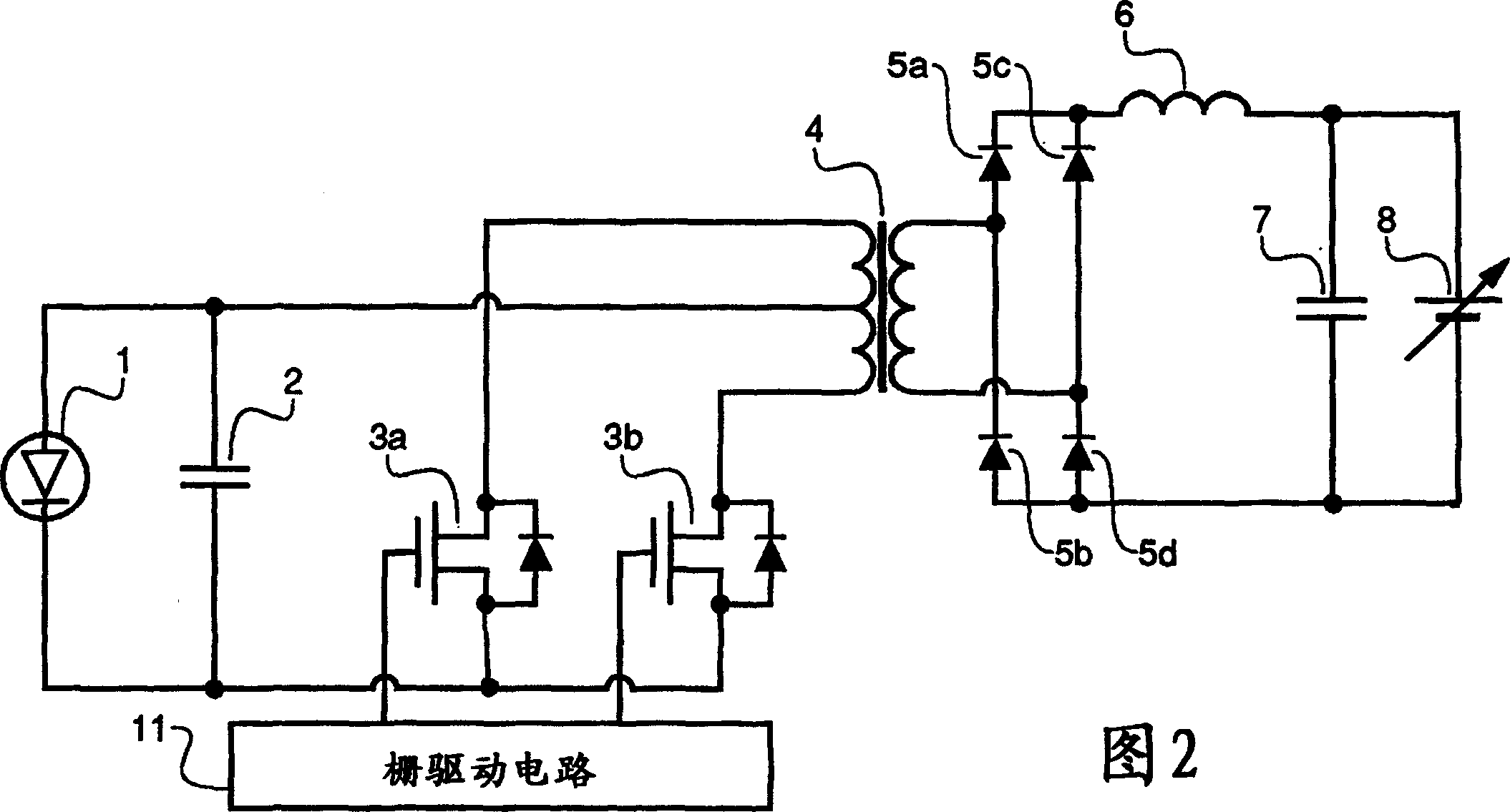
[0055] 6 is a diagram showing a circuit configuration of a solar cell power supply of Example 2. FIG.

[0056] [transformer]

[0057] Figure 11 The specifications of the transformer 4 of the second embodiment are shown.

[0058] The measurement was carried out in the same manner as in Example 1, and the natural vibration frequency of the transformer 4 of Example 2 was 37 kHz, which was much lower than that of the transformer 4 of Example 1. It is presumed that the inductance of the primary coil is incre...

Embodiment 3

[0064] Next, Example 3 will be described. It should be noted that, in the present embodiment, the same reference numerals are used for the same structure as that of the first embodiment, and the detailed description is omitted.

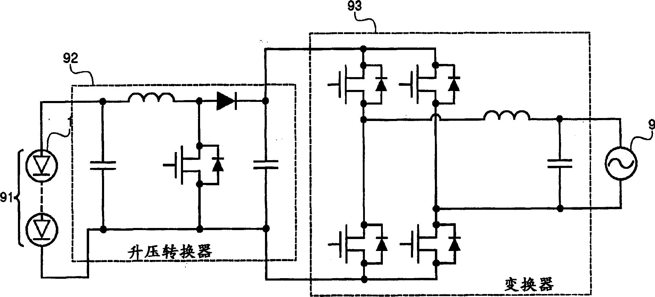
[0065] In Embodiment 3, an example in which the present invention is applied to a system-connected power generation system, which is the mainstream of the current solar power generation system, will be described.

[0066] 8 is a diagram showing a circuit configuration of a solar cell power supply of Example 3. FIG.

[0067] In the third embodiment, 20 solar cell power sources 701 functioning as boost converters are connected in parallel, and the DC output power thereof is supplied to the system-connected inverter 13 and AC power is supplied to the system 9 . That is, system 9 is the load. It should be noted that the solar cell power supply 701 has the same structure as that of the first embodiment except for the transformer 4, and the output thereof...


PUM


Abstract

Although increasing the switching frequency is effective to downsize a power supplying apparatus, the switching loss of a switching element increases if the switching frequency is increased. In a power supplying apparatus including a transformer having a very high boosting ratio, and a plurality of switching elements for supplying AC power to the primary side of the transformer, the frequency of the AC power is set to 0.25 to 2 times the self-resonance frequency of the transformer.

Description

technical field [0001] The present invention relates to a power supply device, a design method thereof, and a power generation device, and in particular, to a power supply device that converts DC power provided by a solar cell. Background technique [0002] The practical application of solar power generation systems has developed rapidly, and many solar power generation systems have been applied in the market. They are power supply devices with high-efficiency power conversion devices using solar cells and switching elements. [0003] figure 1 It is a diagram showing the circuit configuration of the solar cell power supply. The output of the solar cell array 91 is boosted in voltage by a boost converter 92 , converted into AC power by an inverter 93 , and supplied to a commercial power system (hereinafter referred to as “system”) 9 . [0004] In order to miniaturize the converter or converter, it is effective to increase the switching frequency. Even in solar cell power ...

Claims


Application Information

Patent Timeline
IPC IPC(8): H01L31/04H02J7/35H02M3/28H02M3/337H02M7/48
CPCH02J7/35H02M3/3376
Inventor 竹原信善丰村文隆铃井正毅
Owner CANON KK
Why Eureka
Try Eureka