
Acceleration transducer

An acceleration sensor, technology in the thickness direction, applied in the direction of measuring acceleration, velocity/acceleration/shock measurement, using inertial force for acceleration measurement, etc.

Inactive Publication Date: 2003-12-10
MURATA MFG CO LTD
View PDF2 Cites 1 Cited by
  • Summary
  • Abstract
  • Description
  • Claims
  • Application Information

AI Technical Summary

Problems solved by technology

Therefore, the voltage sensitivity of the detection element as a whole is an average value in the longitudinal direction, and the voltage sensitivity as a whole is lower than that of the case where there are electrodes only near the root, so the generated energy cannot be increased.

Method used


Image

  • Acceleration transducer
  • Acceleration transducer
  • Acceleration transducer

Examples


Embodiment Construction

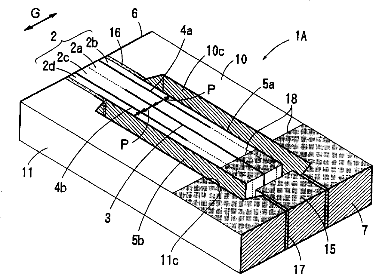
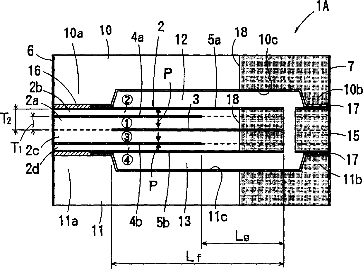
[0043] 1 to 4 show Embodiment 1 of the acceleration sensor of the present invention.

[0044] This acceleration sensor 1A is composed of a pair of support frames (support members) 10 and 11 having a U-shaped cross-section that adhere and support one end portion of the detection element 2 in the longitudinal direction. The support frames 10 and 11 are formed of an insulating material such as ceramics or resin. One end portion of the detection element 2 is bonded and held between the one holding portions 10a, 11a of the support frames 10, 11 with the anisotropic conductive adhesive 16, and between the other holding portions 10b, 11b, each The end member 15 having the same thickness as the detection element 2 is bonded and held by the anisotropic conductive adhesive 17 . Acceleration sensor 1A, in the state that the end part 15 and the detection element 2 are integrally formed, after the two ends are bonded to one support frame 10 (or 11) first, the detection element 2 and the e...


PUM


Abstract

An acceleration sensor includes a sensing element and a pair of supporting members for supporting the sensing element at one end in the longitudinal direction thereof. The sensing element includes four laminated piezoelectric layers, and electrodes are provided at the center in the thickness direction of the sensing element, between a pair of first layers and a pair of second layers, and on the outer surfaces of the pair of second layers. Cells formed by the first and second layers at each side of the center in the thickness direction are electrically connected in parallel. The pair of first layers preferably have substantially the same thickness and the pair of second layers preferably have substantially the same thickness, and the ratio of the thickness T1 of each first layer to the total thickness T2 of each first and second layer is about 62% to about 76%. Therefor, the present invention provide a highly sensitive acceleration sensor in which generated energy can be significantly increased without changing the free length and thickness thereof.

Description

technical field [0001] The present invention relates to an acceleration sensor using piezoelectric ceramics. Background technique [0002] In the past, various proposals have been made for acceleration sensors using piezoelectric ceramics. Generally, in such an acceleration sensor, there are two types of sensitivity, voltage sensitivity and charge sensitivity. The increase in charge sensitivity can improve the S / N ratio against electromagnetic interference from external devices and circuits generated at the connection between the acceleration sensor and the amplifier when the amplifier is connected in the next stage. The increase in voltage sensitivity can improve the S / N ratio of the voltage noise generated by the amplifier itself. Therefore, in order to improve the S / N ratio against both external electromagnetic interference and noise inside the amplifier, it is necessary to increase both the charge sensitivity and the voltage sensitivity. In other words, when the gener...

Claims


Application Information

Patent Timeline
IPC IPC(8): G01P15/09H01L41/08
CPCG01P15/0922
Inventor 多保田纯
Owner MURATA MFG CO LTD
Learn More