Impeller installing structrue of turbocompressor

A technology for a turbo compressor and an installation structure, applied in the field of turbo compressors, can solve problems such as falling off and nut detachment, and achieve the effects of improving assembly efficiency, solid installation structure, and improving reliability.

Inactive Publication Date: 2003-12-17
LG ELECTRONICS (TIANJIN) APPLIANCES CO LTD
View PDF0 Cites 7 Cited by
  • Summary
  • Abstract
  • Description
  • Claims
  • Application Information

AI Technical Summary

Problems solved by technology

[0012] However, the above-mentioned structure has the following disadvantages: if the rotating impeller is stationary, or the stationary impeller is rotating, the nut will be detached from the thread due to inertia during repeated actions.
[0014] However, on the compressor with the above-mentioned structure, when the impeller 30 is stopped by rotation, or is rotated by static, if this action is repeated, the screw 36 on the impeller will move from the screw on the rotating shaft due to inertial factors. drop off on hole 44

Method used


Image

  • Impeller installing structrue of turbocompressor
  • Impeller installing structrue of turbocompressor
  • Impeller installing structrue of turbocompressor

Examples


Embodiment Construction

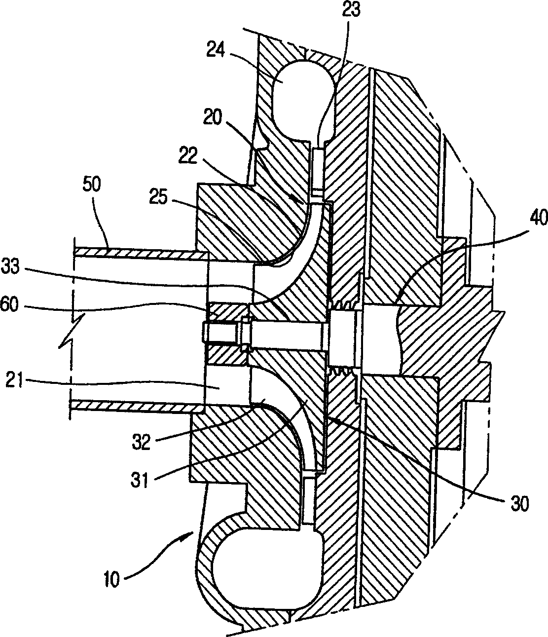
[0026] The impeller installation structure of the turbocompressor of the present invention will be further described in detail in conjunction with the accompanying drawings and specific embodiments: Figure 4 A cross-sectional view showing a compression part of a turbo compressor provided with the turbo compressor impeller mounting structure proposed in the present invention. The description is as follows: First, the compression part of the turbo compressor is provided with a compression chamber 20 connected with the suction passage inside the shell 10 , and a rotatable impeller 70 is inserted into the compression chamber 20 . The impeller 70 is combined with a motor provided inside the casing 10 through a rotating shaft 80 .

[0027] The compression chamber 20 is composed of an induction impeller 21 for introducing gas, an impeller insertion space 22 into which a rotating impeller 70 can be inserted, a diffuser 23 for converting gas kinetic energy into a positive pressure 24 ...


PUM


Abstract

An installation structure for the impeller of turbine compressor features that the hub of vane wheel has multiple fins formed on its external circumference, a join hole with a projected part on its bottom and the first join part on its inner surface, and the motor shaft has a join axle on its end face for inserting it in said hole, which has a slot on its end face for matching with said projected part and the second join part on its external circumference for matching with the first join part. Its advantages are reliable joint and easy assembling.

Description

technical field [0001] The invention relates to the field of turbo compressors. Background technique [0002] Generally speaking, a compressor is a machine that compresses fluid, and consists of a housing with a certain internal space, a motor installed inside the housing to generate driving force, and a large structure such as a compression component that compresses gas. Compressors that compress fluid are divided into various types according to their compression method. [0003] One of the embodiments of the prior art compressor, the action of the turbo compressor is performed through the following steps. After obtaining the driving force generated by the motor, the impeller rotates, and at the same time, the gas is sucked into the compression chamber where the impeller is installed for gas compression, and the high-temperature and high-pressure gas is discharged. [0004] figure 1 Indicates the compression part for compressing gas in the turbo compressor. As shown in t...

Claims


Application Information

Patent Timeline
Patent Type & Authority Applications(China)
IPC IPC(8): F04D29/20F04D29/62
Inventor 崔文畅徐光河金永宽智裕喆王大兴金会善
Owner LG ELECTRONICS (TIANJIN) APPLIANCES CO LTD
Why Eureka
Try Eureka