
Refrigerant pipe structure of air conditioner

A technology for refrigerant pipes and air conditioners, which is applied in the direction of pipe components, pipe layout, pipes/pipe joints/pipe fittings, etc., which can solve the problems of difficult installation of internal components and increase the weight of air conditioners, and achieve simple structure and vibration suppression The effect of convenient transmission and installation

Inactive Publication Date: 2003-12-17
LG ELECTRONICS (TIANJIN) APPLIANCES CO LTD
View PDF0 Cites 3 Cited by
  • Summary
  • Abstract
  • Description
  • Claims
  • Application Information

AI Technical Summary

Problems solved by technology

However, the above method will increase the weight of the air conditioner and cause problems such as difficult installation of internal parts.

Method used


Image

  • Refrigerant pipe structure of air conditioner
  • Refrigerant pipe structure of air conditioner
  • Refrigerant pipe structure of air conditioner

Examples


Embodiment Construction

[0027] The refrigerant pipe structure of the air conditioner of the present invention will be further described in detail below in conjunction with the accompanying drawings and specific embodiments:

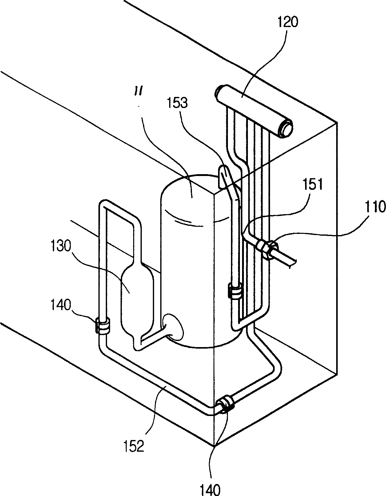
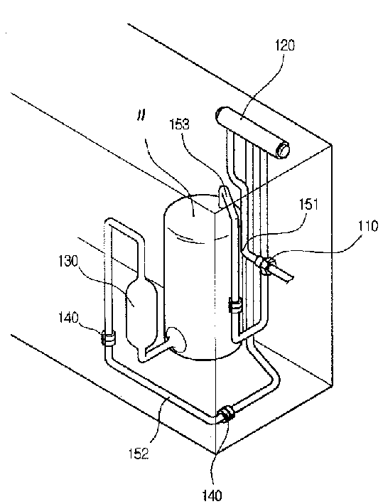
[0028] Such as figure 2 As shown, the refrigerant pipe structure of the air conditioner of the present invention includes: a counterflow pipe 120, a liquid storage tank 130, a rubber sleeve type shock absorber 140, a gaseous refrigerant pipe 151, a refrigerant input pipe 152 and a refrigerant output pipe 153; One end of 152 is connected to the evaporator 21 of the indoor unit 20, the other end is connected to the inlet of the liquid storage tank 130, the outlet of the liquid storage tank 130 is connected to the inlet of the compressor 11 of the outdoor unit 10, and the refrigerant input pipe 152 Several rubber sleeve type shock absorbers 140 are installed; the outlet of the compressor 11 of the outdoor unit 10 is connected with one end of the refrigerant output pipe 153, and th...


PUM


Abstract

A refrigerant pipe structure of air conditioner is composed of countercurrent pipe, liquid accumulator, several vibration dampers for cold medium inlet and outlet tubes, gas-phase cold medium tube connected between countercurrent pipe and condenser, cold medium inlet tube connected between evaporator and liquid accumulator, and cold medium, outlet tube connected between compressor and countercurrent pipe. Its advantages are simple structure and no vibration transfer.

Description

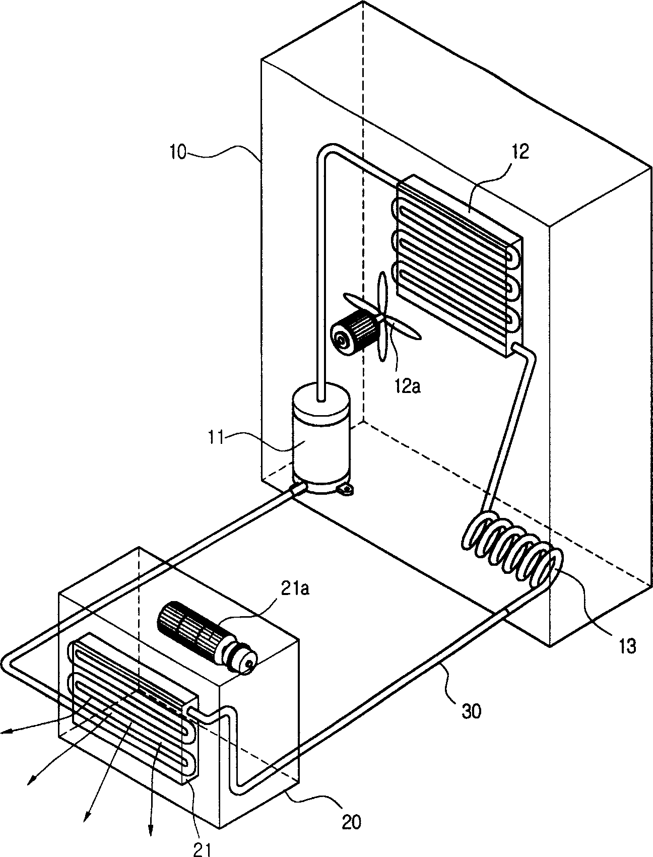
technical field [0001] The invention relates to a component of an air conditioner, in particular to a refrigerant pipe structure of the air conditioner. Background technique [0002] Such as figure 1 As shown, the existing common air conditioner generally includes an outdoor unit 10, a refrigerant pipe 30 and an indoor unit 20; the outdoor unit 10 is installed outdoors to exchange heat with the outdoor air, and the indoor unit 20 is installed indoors to adjust Indoor temperature; the outdoor unit 10 and the indoor unit 20 are connected by a refrigerant pipe 30 . [0003] In more detail, the function of the outdoor unit 10 is to convert the low-temperature and low-pressure gaseous refrigerant flowing from the indoor unit 20 through the refrigerant pipe 30 into a low-temperature and low-pressure liquid refrigerant, and send the low-temperature and low-pressure liquid refrigerant through the refrigerant pipe 30 to the Indoor unit 20. The structure of the outdoor unit 10 incl...

Claims


Application Information

Patent Timeline
Patent Type & Authority Applications(China)
IPC IPC(8): F16L55/02F24F13/02
Inventor 郑寅和宋珍燮陈深元
Owner LG ELECTRONICS (TIANJIN) APPLIANCES CO LTD
Learn More