Mobile information device, method for controlling a mobile information device and program

A technology for mobile information and control units, applied to measuring devices, current supply devices, program control using stored programs, etc., can solve problems such as frequent power switching, device operation, and waste of batteries, and achieve the effect of ensuring user friendliness

Inactive Publication Date: 2004-01-14
FUJITSU LTD
View PDF0 Cites 8 Cited by
  • Summary
  • Abstract
  • Description
  • Claims
  • Application Information

AI Technical Summary

Problems solved by technology

[0009] However, in those devices, if the operating button is pressed while inside a bag or pocket, it causes the device to work
Therefore, causing the device to operate without the user's intentional operation may waste the battery
[0010] In addition, as in the prior art, the scheme of switching the power on and off instantly according to the contact state of the hand or ear etc. involves frequently switching the power on and off in normal mobile information devices.
Therefore, there may be a case where the operation of the user using the mobile information device is interrupted, and the user-friendliness is very poor

Method used


Image

  • Mobile information device, method for controlling a mobile information device and program
  • Mobile information device, method for controlling a mobile information device and program
  • Mobile information device, method for controlling a mobile information device and program

Examples


no. 1 example 》

[0048] Combine below Figures 1 to 6 The mobile information device in the first embodiment of the present invention will be described.

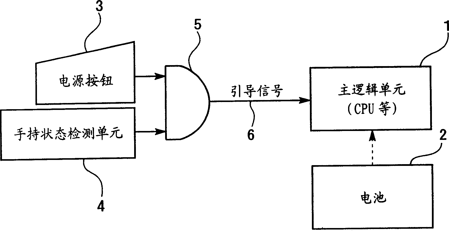
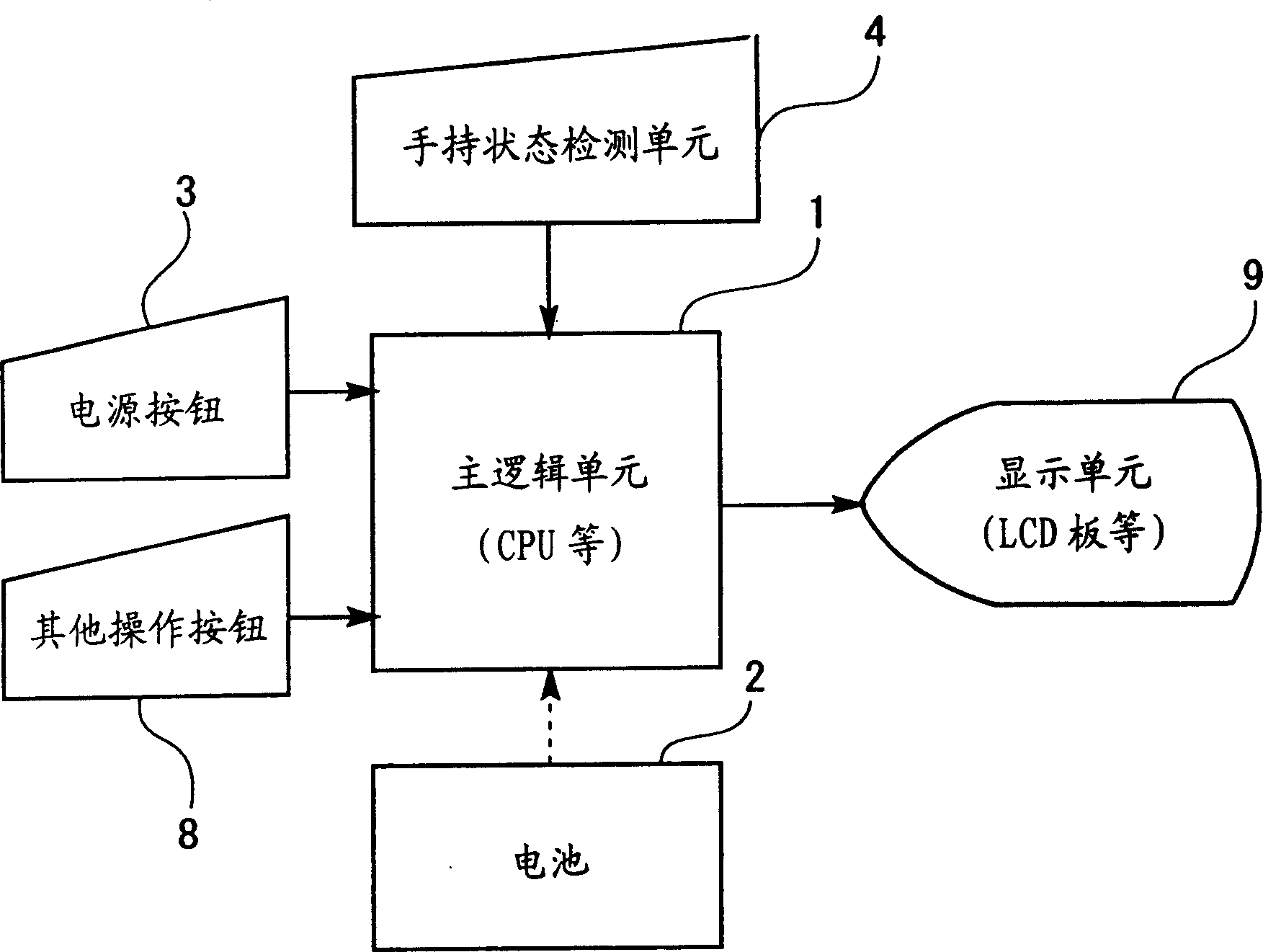
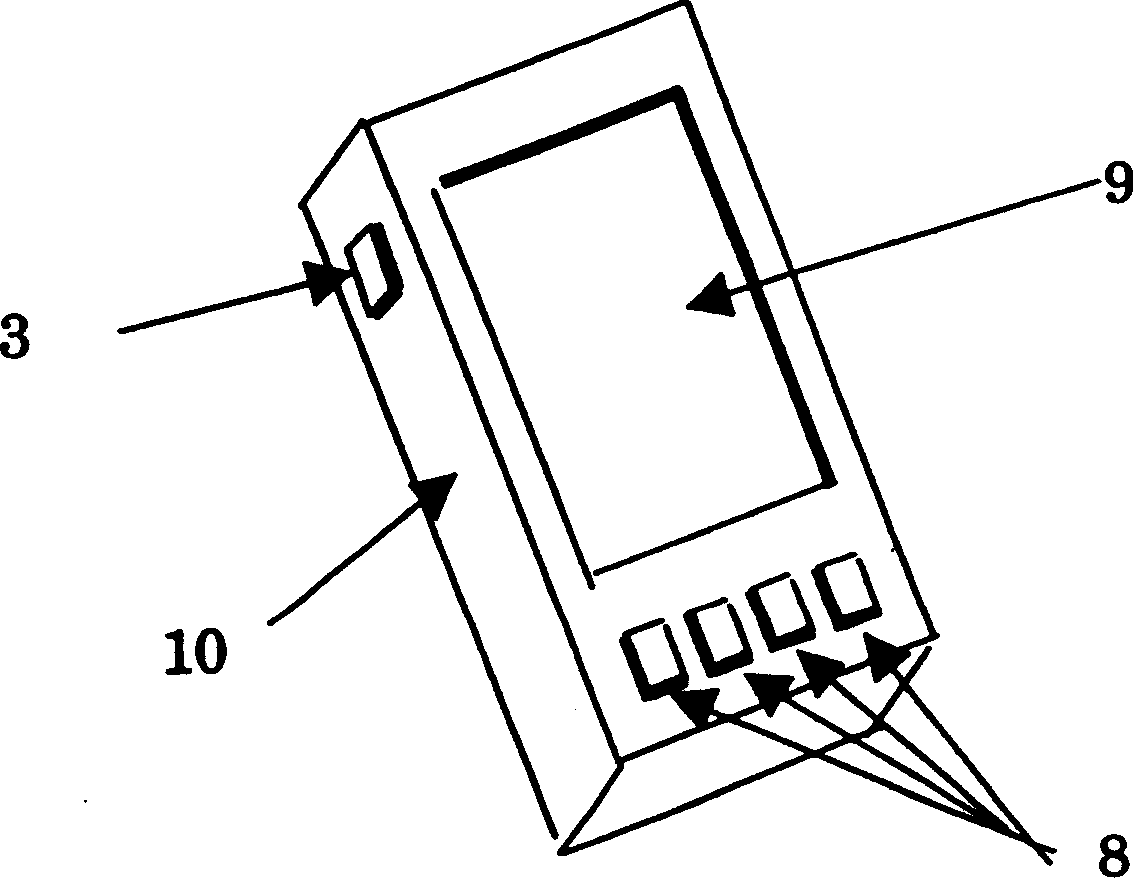
[0049] figure 1 is a logical operation block diagram upon activation of the mobile information device in the first embodiment. figure 2 It is a logical operation block diagram after the mobile information device has been activated. image 3 is the external structure diagram of the mobile information device. Figure 4 is an example diagram of the layout of electrodes installed to detect the hand-held state of the mobile information device. Figure 5 is a flowchart of the hand-held state detection process (1) performed by the main logic unit 1 . Figure 6 is a flowchart of operation detection processing for detecting user operations.

[0050]

[0051] figure 1 Shows the logical operation when the mobile information device is activated. The mobile information device logically includes: a main logic unit 1 for controlling the device; a ...

no. 2 example 》

[0083] Combine below Figures 7 to 9 A mobile information device in a second embodiment of the present invention will be described. Figure 7 It is a flowchart of operation / non-operation state detection processing for detecting whether or not a user operation has been performed. Figure 8 is a flowchart of the hand-held state detection process (2). Figure 9 This is a flowchart of system power OFF processing.

no. 1 example

[0084] According to the first embodiment, when the hand-held state of the mobile information device is detected, the operation of the power button 3 or the operation button 8 is valid. What will be described in the second embodiment are two functions, one function is to automatically stop the system if the operation of the operation button 8 is not detected within a predetermined period of time, and the other function is to detect whether the mobile information device is in the hand-held state to adjust the period before the system is automatically stopped.

[0085] Other configurations and operations are the same as in the first embodiment. Thus, by referring to Figures 1 to 6 Descriptions for the same elements can be easily understood, so descriptions are omitted here.

[0086] Figure 7 It is a flowchart of operation / non-operation state detection processing for detecting whether or not a user operation has been performed. This processing is triggered (started) at predete...


PUM


Abstract

A mobile information device has an operation unit which detects an operation by a user, a detection unit which detects a predetermined state when operated by the user, and a control unit which validates or invalidates the operation of the operation unit, depending on whether the predetermined state is detected or not.

Description

technical field [0001] The invention relates to a mobile information device. Background technique [0002] Many small mobile information devices, such as mobile phones, electronic organizers, PDAs (Personal Digital Assistants) or small personal computers, have been developed, sold and used. This type of mobile information device operates by a built-in battery and can be used in places where it is impossible or difficult to secure a commercial power supply, such as walking, outdoor places, travel destinations, and the like. [0003] The external structure of such a mobile information device has a small size to fit into a pocket of clothes, and its battery capacity is limited. Therefore, it is necessary to reduce the power consumption of the device to achieve long-term work. [0004] For this purpose, a function to reduce power consumption by stopping the operation when the user does not operate the device or turning off the power when no operation of the keyboard or the lik...

Claims


Application Information

Patent Timeline
Patent Type & Authority Applications(China)
IPC IPC(8): G06F1/26G06F1/32G06F15/02H04M1/22H04M1/73
CPCH04M2250/12H04M1/22H04W52/0254Y02D30/70
Inventor 坂本正义
Owner FUJITSU LTD
Why Eureka
Try Eureka