
Phase-transition-liquid bathing heat exchanger

A technology for heat exchangers and heat exchanger tubes, applied in the field of phase change-liquid bath heat exchangers, achieving the effects of high safety, superior regulation performance, and long service life

Inactive Publication Date: 2004-01-28
SHANGHAI UNIVERSITY OF ELECTRIC POWER
View PDF0 Cites 0 Cited by
  • Summary
  • Abstract
  • Description
  • Claims
  • Application Information

AI Technical Summary

Problems solved by technology

[0008] The purpose of the present invention is to overcome the shortcomings of the existing phase change heat exchangers and provide a phase change-liquid bath that can automatically keep the pressure in the heat exchange chamber relatively stable by relying on the change of the liquid level of the heat medium and the change of the heat transfer characteristics of the heat exchange surface. type heat exchanger

Method used


Image

  • Phase-transition-liquid bathing heat exchanger
  • Phase-transition-liquid bathing heat exchanger

Examples


Embodiment Construction

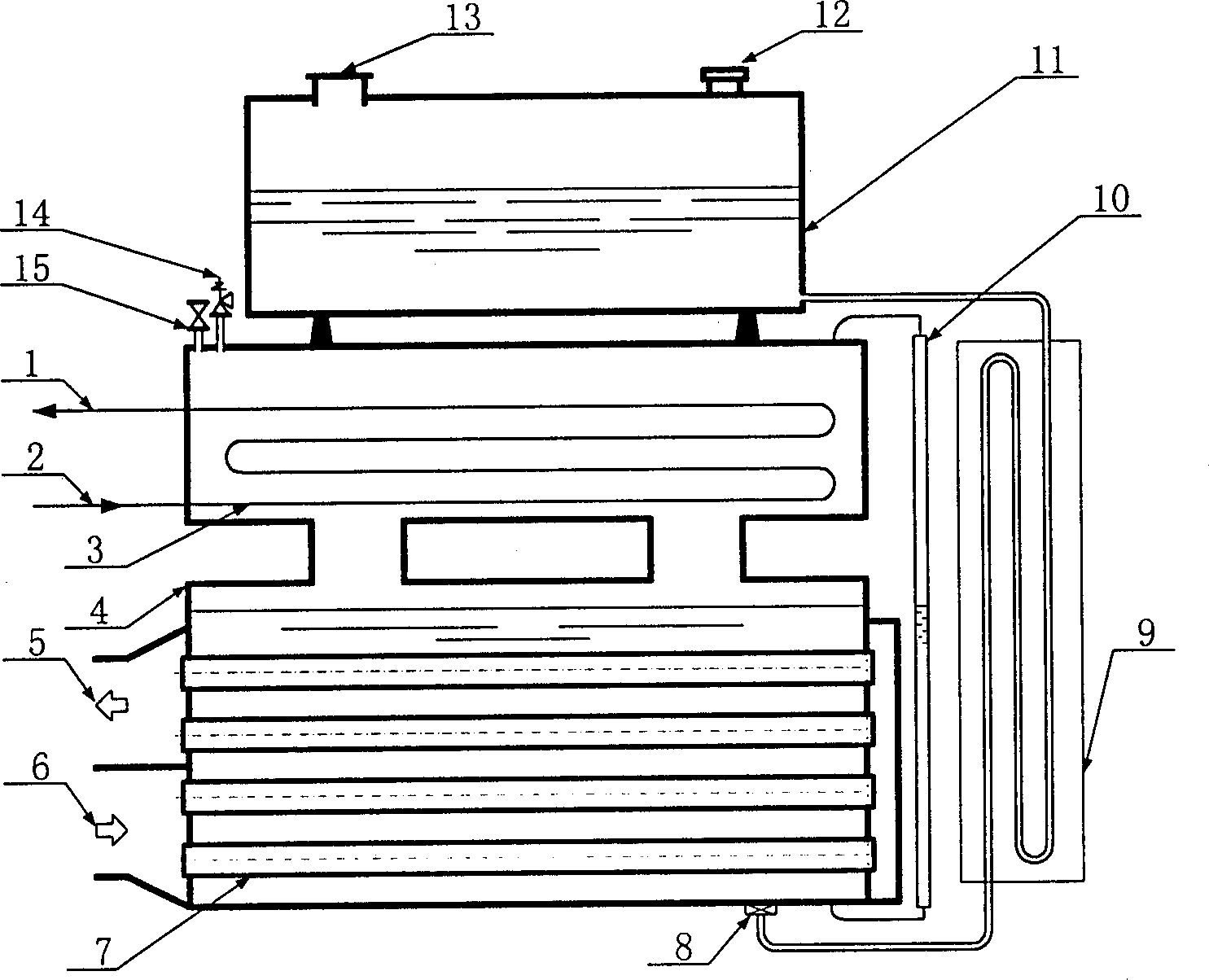
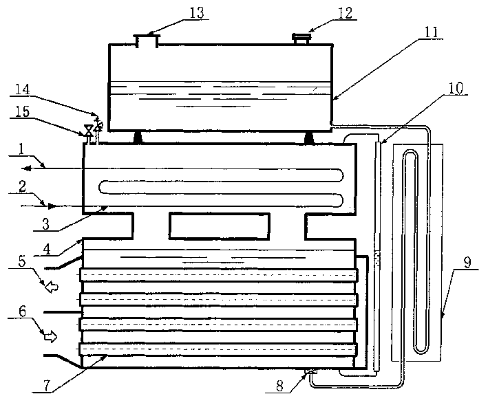
[0024] Depend on figure 1As shown, in the pipeline of the heat exchanger, a heat exchange chamber 4, a gas trap 8, a U-shaped pipe 9, a liquid storage tank 11, and a floating cover 13 are sequentially connected in series, and the top of the heat exchange chamber 4 is equipped with an air release valve 15 And a safety valve 14, a liquid level gauge 10 is installed on the side, a heated fluid heat exchange surface 3 is arranged on the upper part of the heat exchange chamber 4, and a preheated fluid heat exchange surface 7 is arranged on the lower part, the liquid storage tank 11 is located above the top of the heat exchange chamber 4, and its The volume is greater than the sum of the remaining volume of the heat exchange chamber after deducting the space occupied by the heat exchange surface and the volume of the U-shaped tube 9, the floating cover 13 is located on the top of the liquid storage tank 11, and there is a certain gap between the floating cover 13 and the top of the l...


PUM


Abstract

The characters of the heat exchanger are that the recuperator, the choke, the U type tube, the liquid reserve tank and the floating cover are connected in serial in pipe of the heat exchanger. An airrelease valve and a safety valve are at the top part and the fluid level gauge is at side part of the recuperator. Heat transfer surfaces of heated and warm-up liquid are positioned at up and low part respectively. The floating cover is at the top part of the said tank. clean liquid hot media is filled to the recuperator. Based on level change of liquid hot media and the change of heat transfer properties of heat transfer surfaces, 'phase change-liquid bath' type heat exchange can be realized. The invention is applicable to a variety of exchangers, micromidi type boiler providing features of non-fouling, low consumption of hot media without need of air extractor and additional embalmment.

Description

technical field [0001] The invention relates to a heat exchange device in which the heat exchange medium does not directly contact, in particular to a phase change-liquid bath heat exchanger. Background technique [0002] Phase change heat exchangers can be used in a wide range of industrial fields such as power, petroleum, chemical, pharmaceutical, and food. The most typical phase change heat exchanger is a phase change boiler. According to the pressure in the phase change heat chamber, phase change boilers can be divided into three types: vacuum phase change boilers, pressure phase change boilers and atmospheric phase change boilers. Although these three existing phase change boilers all have the advantages of no dry burning of the heat exchange surface, no fouling in the furnace, and long service life, they share the following significant disadvantages: [0003] (1) Poor adjustability. When the heat required by the heated fluid decreases, for example, when the flow rat...

Claims


Application Information

Patent Timeline
IPC IPC(8): F24H7/02
Inventor 姚秀平齐进郑莆燕王启杰张莉
Owner SHANGHAI UNIVERSITY OF ELECTRIC POWER
Learn More