
Gas pressure valve

A gas pressure and valve body technology, applied in the mechanical field, can solve the problems of cumbersome processing technology, limited service life, abnormal pressure, etc., and achieve the effects of good toughness, maintaining stability, and convenient assembly and disassembly.

Inactive Publication Date: 2015-06-10
NINGBO YONGSHOCK PRECISION MACHINERY COMPANY
View PDF11 Cites 0 Cited by
  • Summary
  • Abstract
  • Description
  • Claims
  • Application Information

AI Technical Summary

Problems solved by technology

However, the use of the existing technology is prone to the following problems, such as air leakage of the pressure valve caused by the aging and wear of the sealing component; abnormal pressure caused by the expansion and deformation of the sealing component, etc.
[0003] In addition, the existing gas pressure valves on the market are basically made of metal materials. Although this kind of pressure valve has high strength and hardness, it is heavy, easy to corrode, has a limited service life, and the processing technology is cumbersome. , higher production costs

Method used


Image

  • Gas pressure valve
  • Gas pressure valve
  • Gas pressure valve

Examples


Embodiment 1

[0054] Weigh the raw materials according to the composition and parts by weight of the valve body and ventilation gas in Example 1 in Table 1, wherein the reinforcing fiber is an aramid fiber with a diameter of 3-5 μm and an aspect ratio of (50-100): 1 ; The filler is Al with a particle size of 30-50nm 2 o 3 . Then put all the raw materials into a high-speed mixer and mix evenly to obtain the material. Then the material is put into the feeding hopper of the twin-screw extruder, and fed into the twin-screw extruder by the feeding hopper. The temperature of the twin-screw extruder is controlled at 180°C, and the screw speed is 30r / min. Extrude from the head of the machine. Then granulate through a granulator to obtain pellets. The pellets are then added to the barrel of the injection molding machine, heated to a molten state, and then the molten material is injected into a mold at a temperature of 40°C through a nozzle with a temperature of 160°C, the injection pressure is 8...

Embodiment 2

[0056] The raw materials are weighed according to the composition and parts by weight of the valve body and venting gas of Example 2 in Table 1, wherein the reinforcing fiber is a glass fiber with a diameter of 5-8 μm and an aspect ratio of (100-200): 1; The filler is TiO with a particle size of 50-80nm 2 . Then put all the raw materials into a high-speed mixer and mix evenly to obtain the material. Then put the material into the feeding hopper of the twin-screw extruder, and feed it into the twin-screw extruder by the feeding hopper. The temperature of the twin-screw extruder is controlled at 200°C, and the screw speed is 40r / min. Extrude from the head of the machine. Then granulate through a granulator to obtain pellets. The pellets are added to the barrel of the injection molding machine, heated to a molten state, and then the molten material is injected into a mold at a temperature of 45°C through a nozzle at a temperature of 180°C, with an injection pressure of 90MPa a...

Embodiment 3

[0058] Weigh the raw materials according to the composition and parts by weight of the valve body and the ventilation gas of Example 3 in Table 1, wherein the reinforcing fiber is a carbon fiber with a diameter of 3-8 μm and an aspect ratio of (80-200): 1; filler CaCO with a particle size of 30-80nm 3 . Then put all the raw materials into a high-speed mixer and mix evenly to obtain the material. Then the material is put into the feeding hopper of the twin-screw extruder, and fed into the twin-screw extruder by the feeding hopper. The temperature of the twin-screw extruder is controlled at 210°C, and the screw speed is 50r / min. Extrude from the head of the machine. Then granulate through a granulator to obtain pellets. The pellets are added to the barrel of the injection molding machine, heated to a molten state, and then the molten material is injected into a mold at a temperature of 50°C through a nozzle at a temperature of 190°C, with an injection pressure of 95MPa and an...


PUM

PropertyMeasurementUnit
diameteraaaaaaaaaa
particle diameteraaaaaaaaaa
diameteraaaaaaaaaa

Abstract

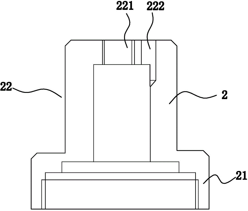
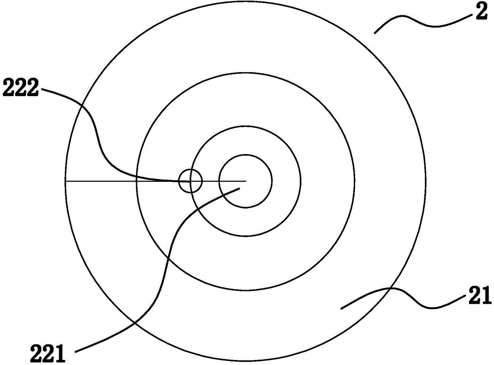
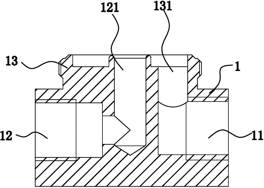
The invention relates to a gas pressure valve which includes a valve body and a ventilation body, wherein the valve body comprises a top surface, a bottom surface and side surfaces; a gas inlet and a gas outlet are formed in the side surfaces; a mounting table vertically protrudes from the top surface; a gas inlet hole and a gas outlet hole are formed in the mounting table; the gas inlet hole is communicated with the gas inlet; the gas outlet hole is communicated with the gas outlet; the ventilation body comprises a connecting part which is connected to the mounting table through threads; the top of the mounting table and the top of the connecting part are recessed to form cavities; the top surface of the connecting part vertically protrudes to form a ventilation part; the ventilation part is hollow and is communicated to the cavities; threaded holes are formed in the top surface and are used for communicating the external world with the inner part of the ventilation part; a groove is formed in the inner surface of the ventilation part and is used for communicating the external world with the inner part of the ventilation part; the valve body and the ventilation body are both made of PE composite materials. The gas pressure valve solves the problems of gas leakage and abnormal pressure of the conventional gas pressure valves, and has the advantages of being good in sealing performance, good in stability, firm in structure, light in weight, high in corrosion resistance and the like.

Description

technical field [0001] The invention belongs to the technical field of machinery, and relates to an operating device, in particular to a gas pressure valve. Background technique [0002] The gas pressure valve plays the role of reducing the output pressure and stabilizing the output pressure, and is an important gas equipment in the matching of gas appliances. In the prior art, the pressure valve is generally composed of an air inlet, an air outlet, a hand wheel, an upper valve cover, a lower valve cover, an air inlet nozzle, a breathing hole, an upper air chamber, a decompression chamber, a valve pad and the like. However, the following problems are prone to occur when using the existing technology, such as air leakage of the pressure valve caused by the aging and wear of the sealing component; abnormal pressure caused by the expansion and deformation of the sealing component. [0003] In addition, the gas pressure valves currently on the market are basically made of metal...

Claims


Application Information

Patent Timeline
Patent Type & Authority Applications(China)
IPC IPC(8): F16K27/00C08L23/06C08L77/10C08K13/04C08K7/06C08K7/14B29C45/00
CPCF16K27/00B29C45/00C08K7/06C08K7/14C08K13/04C08L23/06C08L77/10
Inventor 李再裕陈旗
Owner NINGBO YONGSHOCK PRECISION MACHINERY COMPANY
Learn More