Apparatus for controlling fluorescent lamp and scanning device having same

A technology for fluorescent lamps and control units, applied in the field of devices for controlling fluorescent lamps, capable of solving problems such as high power consumption, inability to control application variablely, long initial warm-up time, etc.

Inactive Publication Date: 2004-01-28
SAMSUNG ELECTRONICS CO LTD
View PDF0 Cites 6 Cited by
  • Summary
  • Abstract
  • Description
  • Claims
  • Application Information

AI Technical Summary

Problems solved by technology

Therefore, the conventional fluorescent lamp control device cannot variably control the voltage applied to the fluorescent lamp, and it takes a long time for the fluorescent lamp to start operating due to a long initial warm-up time, which reduces the lifetime and also results in high power consumption.

Method used


Image

  • Apparatus for controlling fluorescent lamp and scanning device having same
  • Apparatus for controlling fluorescent lamp and scanning device having same
  • Apparatus for controlling fluorescent lamp and scanning device having same

Examples


Embodiment Construction

[0025] Embodiments of the invention will be described in detail and examples of the invention will be illustrated in the accompanying drawings, in which like reference numerals refer to like elements throughout. The embodiments are described below in order to explain the present invention by referring to the figures.

[0026] In the following, reference will be made to figure 2 An embodiment of the present invention will be described. In the following description of the present invention, when a detailed description of known functions and structures incorporated herein makes the subject matter of the present invention more unclear, it will be omitted.

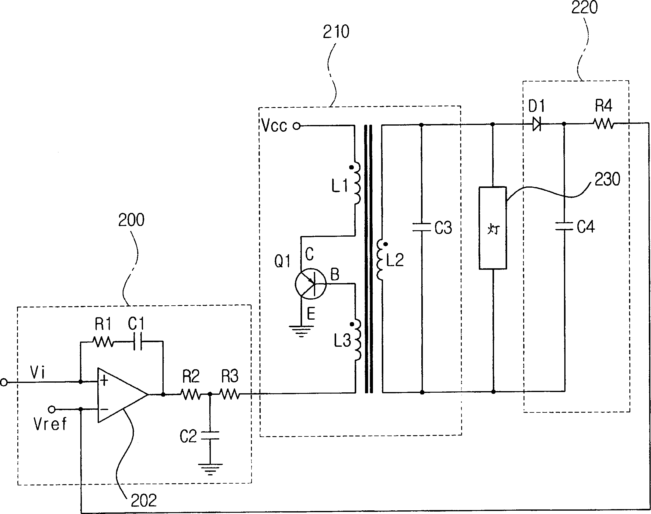
[0027] figure 2 is a circuit diagram illustrating an apparatus for controlling a fluorescent lamp according to an embodiment of the present invention. Such as figure 2 As shown, the device for controlling a fluorescent lamp includes a control unit 200 , a driving unit 210 and a feedback unit 220 .

[0028] The feedback uni...


PUM


Abstract

An apparatus controlling a cold cathode fluorescent lamp and a scanning apparatus having the same are disclosed. The scanning apparatus including the fluorescent lamp and a scan unit comprises: a central processing unit (CPU) controlling the scan unit to be in one of the stand-by mode, the scan mode and the sleep mode and outputting a square signal having a variable duty ratio based on the operation mode of the scan unit; a rectifying unit receiving the square wave signal from the CPU, rectifying the square wave signal into the level of DC voltage based on the duty ratio of the square wave signal, and outputting the rectified DC voltage; a feedback unit detecting the voltage applied to the fluorescent lamp and outputting the detected voltage as a feedback signal; a controlling unit controlling the illumination of the fluorescent lamp based on the voltage that is inputted from the feedback unit, the controlling unit outputting a control signal variably controlling the voltage applied to the fluorescent lamp depending on the level of DC voltage that is inputted from the rectifying unit; and a drive unit applying variable AC voltage to the fluorescent lamp based on the control signal that is inputted from the controlling unit, thereby driving the fluorescent lamp.

Description

technical field [0001] The present invention generally relates to a device for controlling a fluorescent lamp and a scanning device having the same, and more particularly to a device capable of variably controlling a fluorescent lamp and a scanning device having the same. Background technique [0002] CCFLs are widely used as backlights to illuminate display panels such as liquid crystal displays used as displays in portable notebook computers, etc., or as light sources to continuously illuminate originals in scanning devices. [0003] In order to drive a cold cathode fluorescent lamp, generally a pulse wave is generated by a switching device such as a transistor, and the generated pulse wave is raised to a high voltage having a frequency equal to or greater than 200 KHz and an effective value exceeding 500 volts in a coil type transformer, This voltage is applied to cold cathode fluorescent lamps. The operation of a conventional fluorescent lamp control device will be desc...

Claims


Application Information

Patent Timeline
Patent Type & Authority Applications(China)
IPC IPC(8): H05B41/38H05B41/282H05B41/392
CPCH05B41/2821H05B41/392H05B41/38
Inventor 柳汉青秋钟杨
Owner SAMSUNG ELECTRONICS CO LTD
Why Eureka
Try Eureka