Connector with plural switching assemblies of compatible interface

A connector and interface technology, applied in the direction of connection, fixed connection, two-part connection device, etc., can solve problems such as limiting the maximum clock speed data transmission speed and affecting signal quality.

Inactive Publication Date: 2004-02-04
INFINEON TECH AG
View PDF0 Cites 3 Cited by
  • Summary
  • Abstract
  • Description
  • Claims
  • Application Information

AI Technical Summary

Problems solved by technology

[0012] In the form of electrical signal lines between bus control modules, the connectors and possible termination points affect the quality of the signals on the signal lines and limit the maximum clock speed and associated data on the signal lines transfer speed

Method used


Image

  • Connector with plural switching assemblies of compatible interface
  • Connector with plural switching assemblies of compatible interface
  • Connector with plural switching assemblies of compatible interface

Examples


Embodiment Construction

[0045] The first figure to the fourth figure refer to a personal computer (PC) system, and its main memory can be configured by using a magnetic grid as a memory module and a preset insertion position on the motherboard. However, the design versatility of the connector of the present invention will be apparent to those skilled in the art.

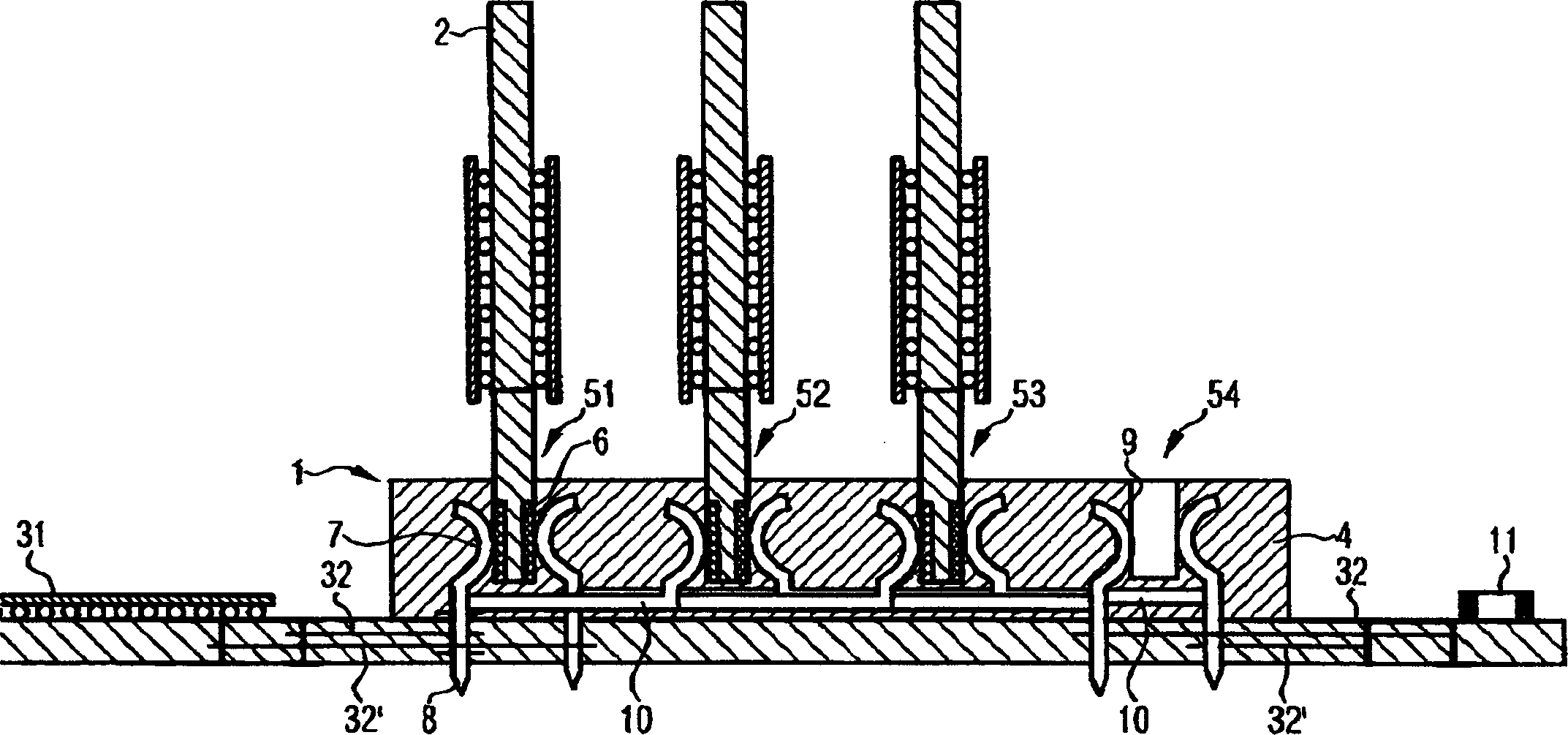
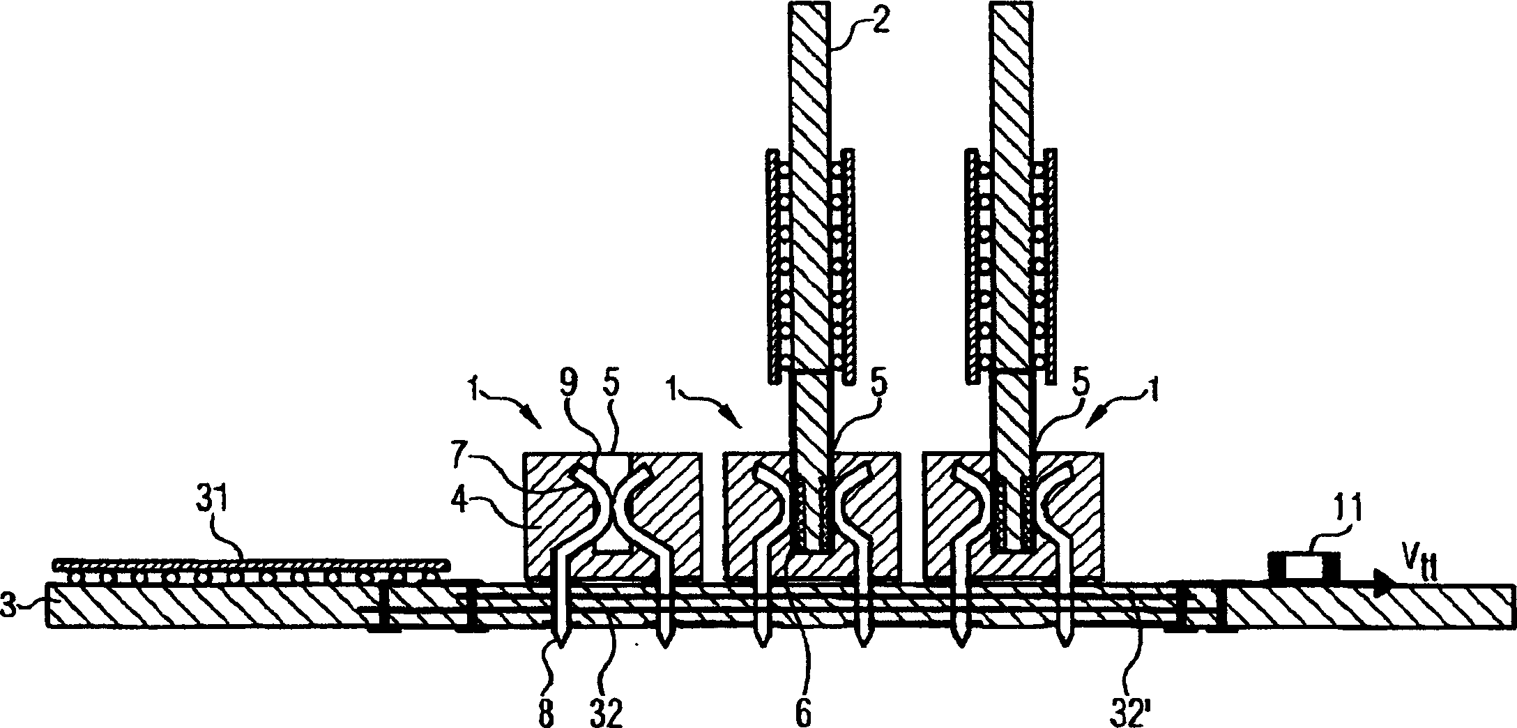
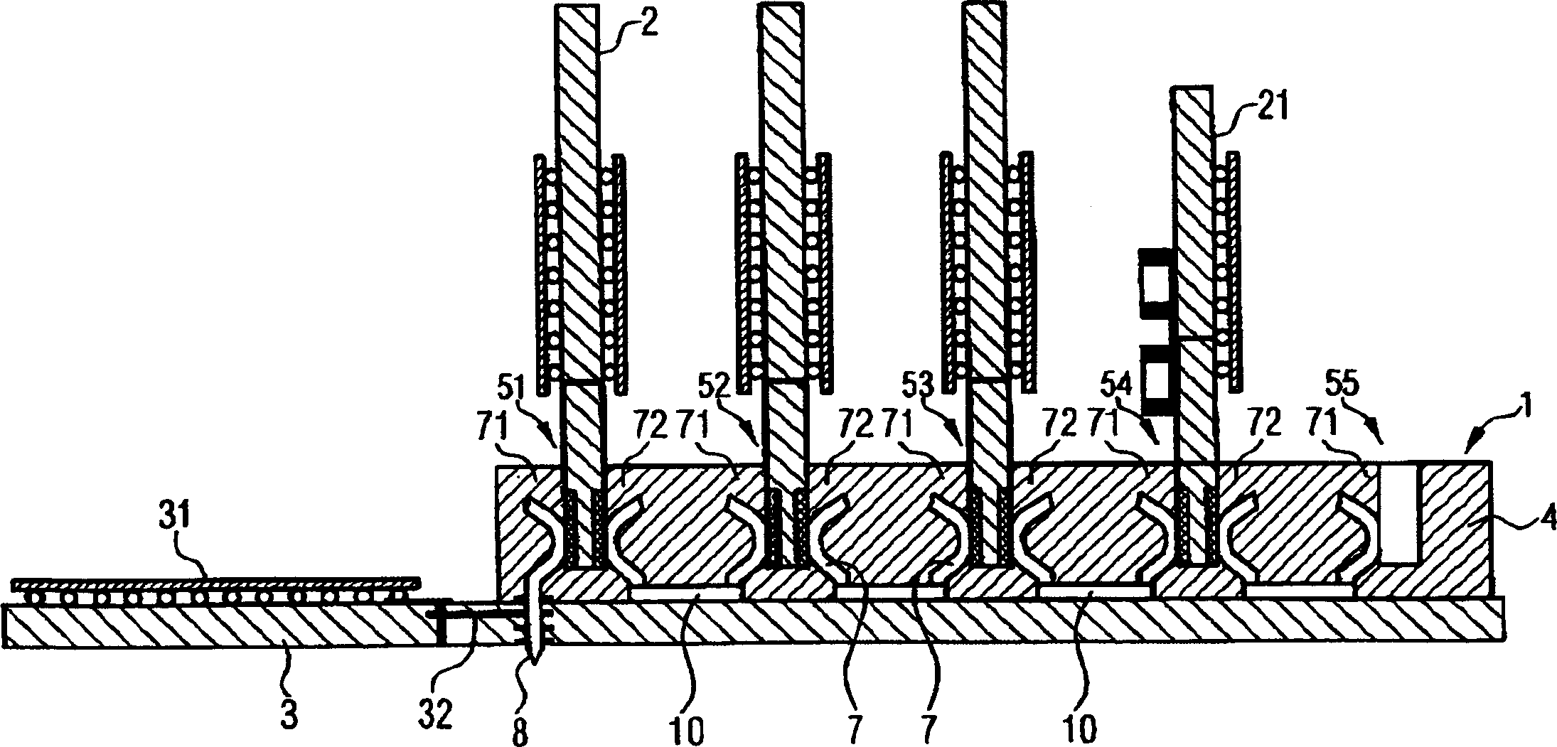
[0046] In the conventional arrangement shown in the second figure, a bus control module 31 , a plurality of connectors 1 , and termination points 11 are arranged on a main board such as the substrate 3 . The bus control module 31, the plurality of connectors 1, and the termination point 11 are electrically connected to each other through a signal line 32 of a stub module bus system. The contact assembly 7 is connected to a corresponding contact device 8, which in this example is shaped as a contact pin. The two connectors 1 on the right are equipped with a switching combination 2 with a contact area 6 . In this configuration, one of the s...


PUM


Abstract

A connector is described for fixing a plurality of switching assemblies on a substrate. The connector is also for making contact with the plurality of switching assemblies, which have compatible interfaces. The connector has a plurality of receptacle devices with contact elements and internal contact connections between corresponding contact elements, as a result of which, the length of the connections between the switching assemblies is reduced, signal propagation times are shortened and a higher clock rate for operating the switching assemblies is made possible.

Description

technical field [0001] The present invention is a connector for positioning and making contact on a substrate with a switching combination having contact areas and mutually compatible interfaces, comprising an insulator formed on the insulator as the The plurality of socket devices arranged in the exchange combination, the contact components arranged in the inner area of ​​the socket device and opposite to the corresponding contact areas on the exchange combination, and the contact devices are used for disposing on the substrate or The signal lines within make electrical contact. Background technique [0002] Modular electrical systems in various configurations are often provided with motherboards having one or more magnetic compartments. According to the requirements of the system or the expansion level of the system, these magnetic grids are respectively configured with a modular component or left empty. In this case, the interfaces of these modular components need to be...

Claims


Application Information

Patent Timeline
Patent Type & Authority Applications(China)
IPC IPC(8): H01R12/16H01R12/18H01R12/71H01R13/66H01R13/68H01R24/00
CPCH01R12/52H01R12/716
Inventor H·鲁克鲍尔M·库滋门卡
Owner INFINEON TECH AG
Why Eureka
Try Eureka