Non-volatile storage device and control method thereof

A technology of non-volatile storage and control method, applied in the field of non-volatile storage device and its control, can solve problems such as time increase, and achieve the effect of high-speed and high-efficiency control

Inactive Publication Date: 2004-02-04
PANASONIC CORP
View PDF0 Cites 3 Cited by
  • Summary
  • Abstract
  • Description
  • Claims
  • Application Information

AI Technical Summary

Problems solved by technology

That is, after a portable device is inserted into a non-volatile storage device, the time required for the portable device to recognize the non-volatile storage device increases, that is, the time during which the user cannot operate the portable device increases, which has become a problem.

Method used


Image

  • Non-volatile storage device and control method thereof
  • Non-volatile storage device and control method thereof
  • Non-volatile storage device and control method thereof

Examples


Embodiment 1

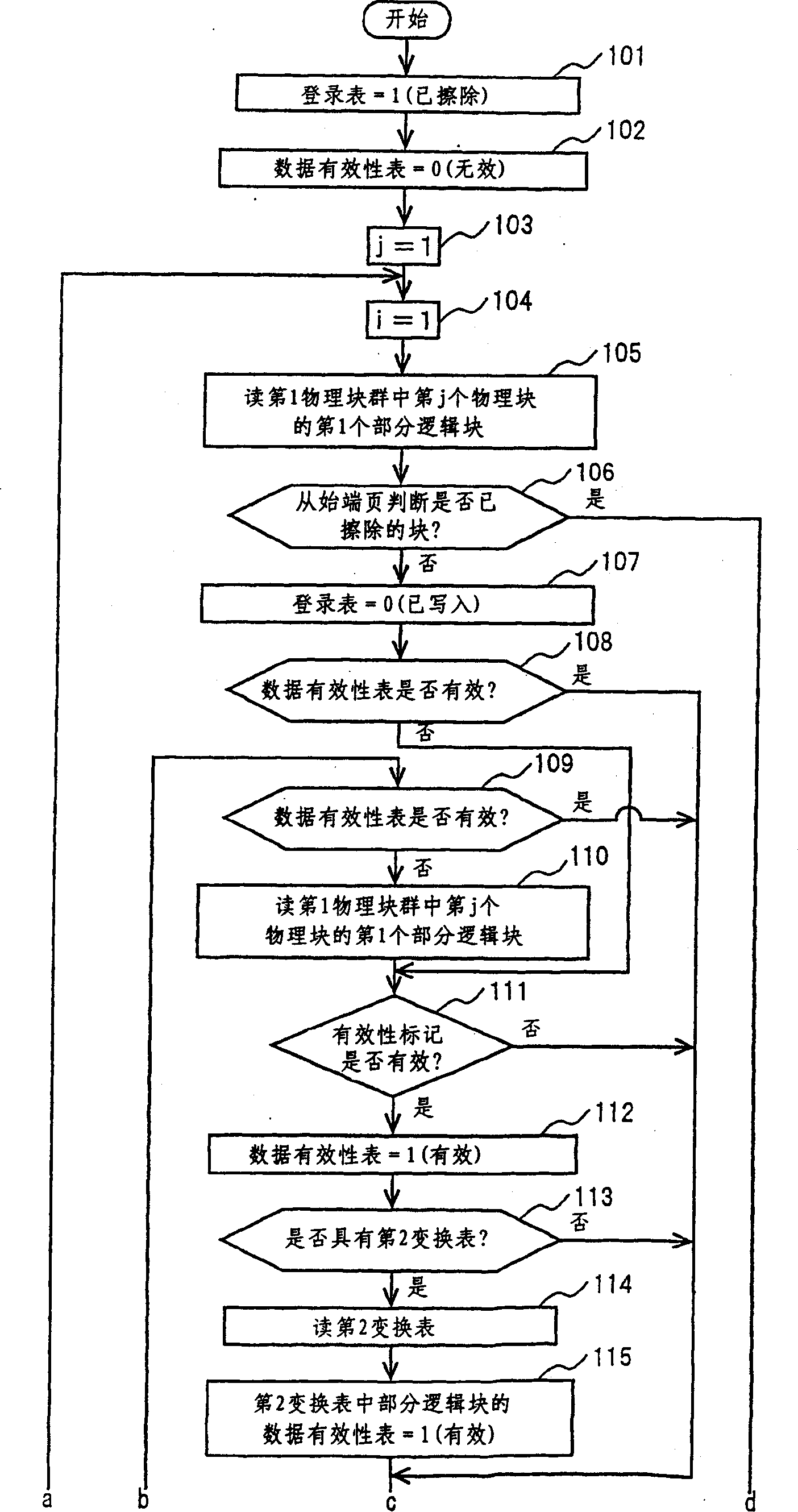
[0066] The nonvolatile memory device of the first embodiment of the present invention has the structure shown in the figure. The control unit 3 of the nonvolatile storage device of the first embodiment has the first table compiling means for compiling the first conversion table 4, and compiles the second table compiling of the second conversion table in partial logical blocks of the nonvolatile storage medium 2. Means, the preparation of the third table of the registration form (table 3) 6 and the preparation of the fourth table of the data validity table (the 4th table) (Figure 4 Shown in).

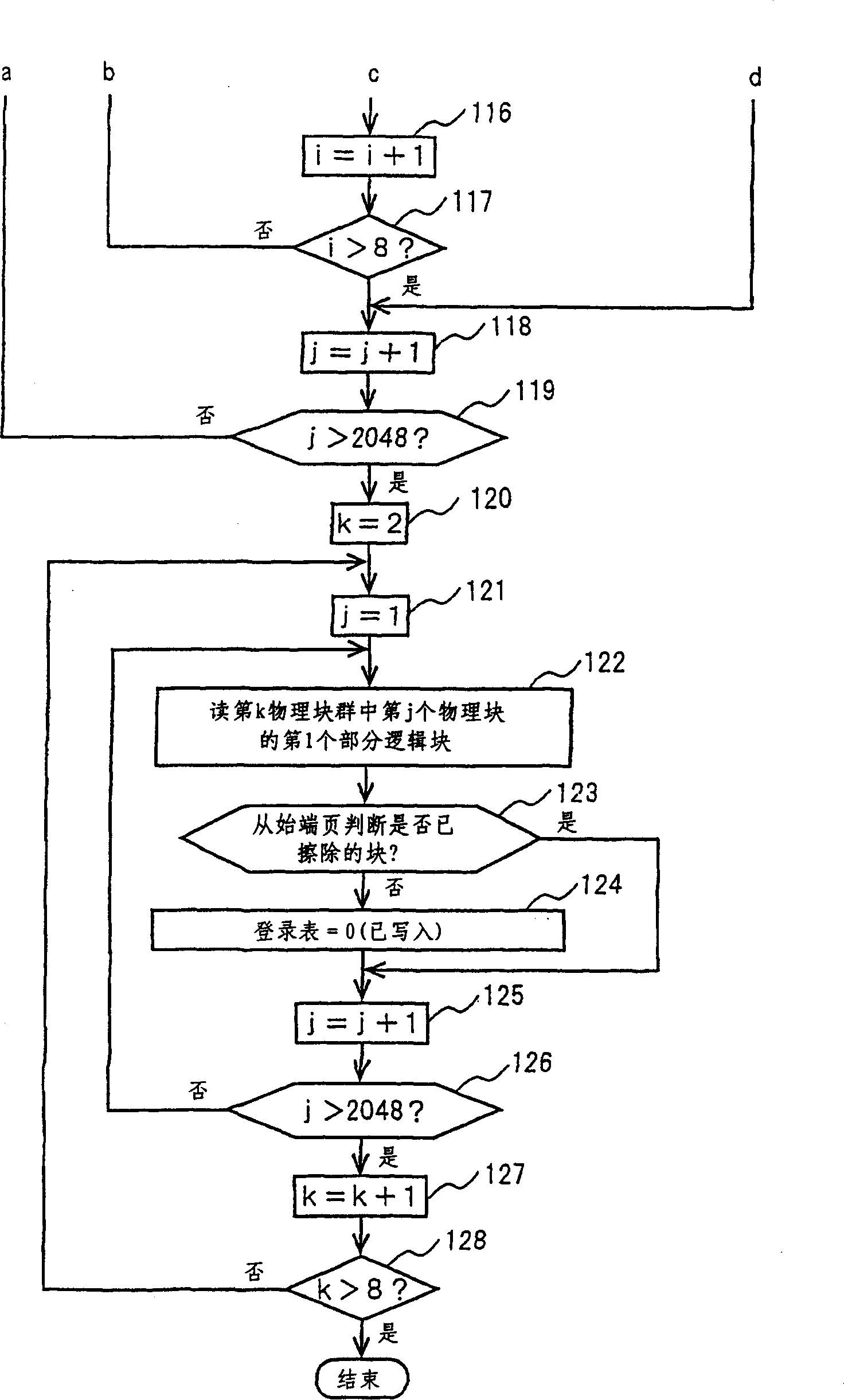
[0067] Figure 1A , Figure 1B It is a flowchart executed by the third table compiling means and the fourth table compiling means at the time of initialization of the nonvolatile storage device of the first embodiment of the present invention. Figure 1A versus Figure 1B in Figure 1A A and Figure 1B Of a, Figure 1A B and Figure 1B B, Figure 1A C and Figure 1B C, Figure 1A D and Fig...

Embodiment 2

[0083] The non-volatile storage device of the second embodiment of the present invention has the same components as the non-volatile storage device of the first embodiment ( Figure 4 ). Except for the following points, the nonvolatile storage device of the second embodiment is the same as the nonvolatile storage device of the first embodiment.

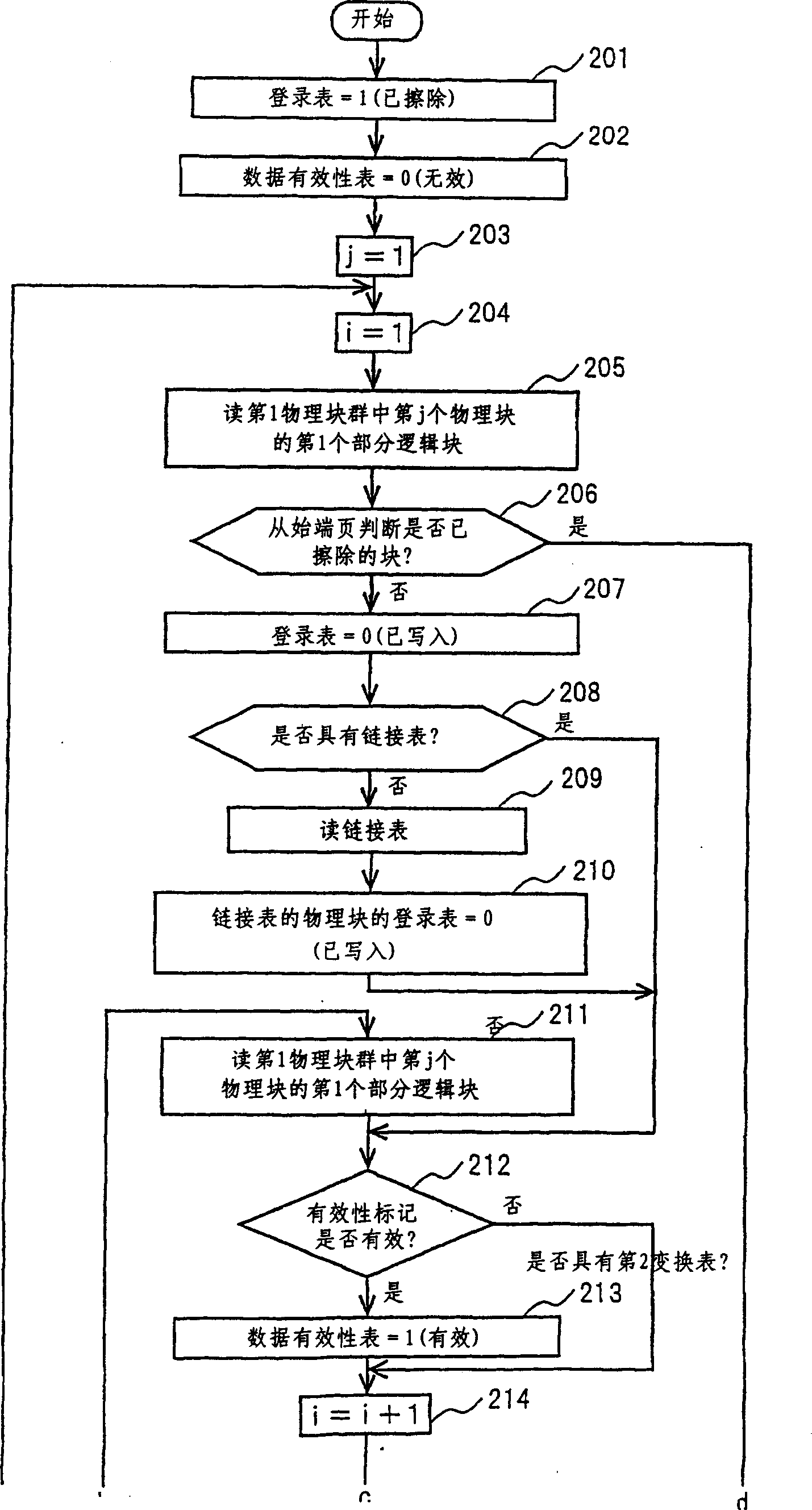
[0084] Figure 2A , Figure 2B It is a flowchart executed by the third table compiling means and the fourth table compiling means at the time of initialization of the non-volatile storage device of the second embodiment of the present invention. Figure 2A versus Figure 2B in Figure 2A A and Figure 2B Of a, Figure 2A B and Figure 2B B, Figure 2A C and Figure 2B C, Figure 2A D and Figure 2B D and other 4 connections.

[0085] Figure 2A , Figure 2B In step 201, the third table compiling means sets an initial value of 1 (erased) for all the columns of the registration table. In step 202, the fourth table compiling means sets an ...

Embodiment 3

[0098] The non-volatile storage device of the third embodiment of the present invention has the same components as the non-volatile storage device of the first embodiment ( Figure 4 ). Except for the following points, the nonvolatile storage device of the third embodiment is the same as the nonvolatile storage device of the first embodiment.

[0099] Picture 11 22 is a flowchart of the third table compiling means executed during initialization of the non-volatile storage device according to the third embodiment of the present invention.

[0100] Picture 11 In step 1101, the third table compiling means sets an initial value of 1 (erased) in all the fields of the registration table. In step 1102, the control unit 3 sets an initial value of 1 to the physical block group number K. In step 1103, the control unit 3 sets an initial value of 1 for the physical block number j in the physical block group.

[0101] In step 1104, the control unit 3 determines whether or not the registratio...


PUM


Abstract

The invention provides a non-volatile memory device capable of improving the convenience of portable apparatus by reducing initialization time and the control method thereof. In generating the table of data validity at the time of initialization, the control section reads the validity flag and the second conversion table. When the validity flag is valid, the logical block of the second conversion table is also valid. Consequently, the fourth table generating means can set all the logical blocks on the second conversion table valid for the table of data validity. Therefore, the fourth table generating means can conduct setting of a plurality of logical blocks by reading only once as mentioned above. Furthermore, in regard to the partial logical block set valid for the table of data validity, reading of the validity flag can be omitted and be forwarded to process the next partial logical block.

Description

Technical field [0001] The present invention relates to a non-volatile storage device and a control method thereof. Background technique [0002] As storage devices for portable devices that process music data and image data, storage devices with nonvolatile memories such as flash memory that can rewrite data, are highly portable, and do not require a battery, etc. have been used. [0003] use Figure 4 to Figure 10 Take the case of four 512 Mbit flash memory chips with a capacity of 256 MB as an example to illustrate the existing non-volatile storage device. [0004] Figure 4 It is a block diagram of a non-volatile storage device. [0005] Figure 4 Among them, 1 is a non-volatile storage device, and 8 is a data input / output device. The non-volatile storage device 1 has a non-volatile storage medium 2 (flash memory in existing examples and embodiments of the present invention), and a control unit 3. The control unit 3 has a first conversion table (indirect conversion table) 4...

Claims


Application Information

Patent Timeline
Patent Type & Authority Applications(China)
IPC IPC(8): G11C16/02G06F12/00G06F12/02
CPCG06F12/0246G06F12/02
Inventor 本多利行笠原哲志外山昌之明石輝夫坂井敬介
Owner PANASONIC CORP
Why Eureka
Try Eureka