

Fine punching mold frame
A technology of fine punching die and mold base, which is applied in the field of tooling and mold in sheet metal fine punching technology, which can solve the problems of high cost, punching and blanking, etc., and achieve the effect of low cost, adjustable elasticity and good rigidity
- Summary
- Abstract
- Description
- Claims
- Application Information
AI Technical Summary
Problems solved by technology
Method used
Image

Examples
Embodiment 1
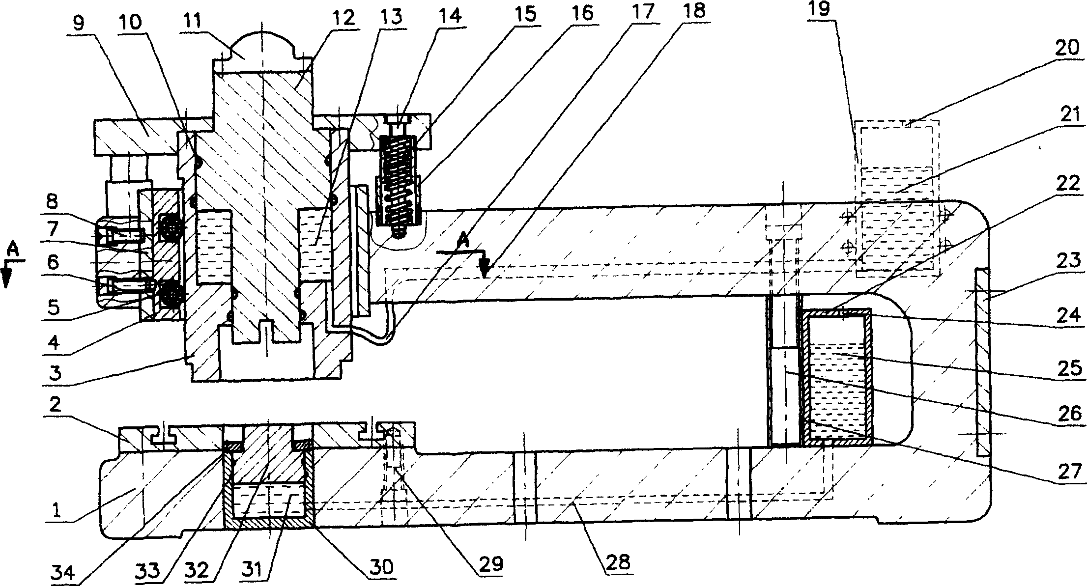
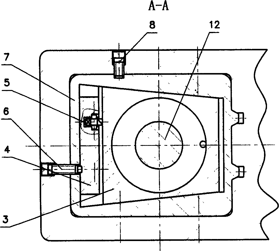
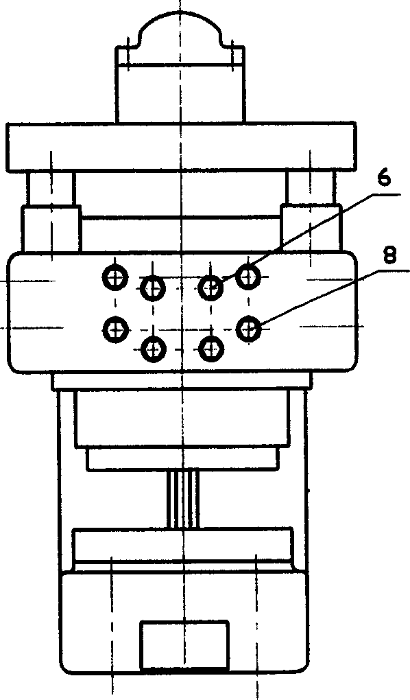
[0026] Thin plate unidirectional blanking formwork and die structure and its blanking process (see Figure 5 ): a fine-blanking die frame, on the upper arm of the U-shaped die frame main body 1 is equipped with an upper pressure head 11, an upper gland 9, a pre-pressure coil spring 15, a blanking die set 3 and a punch handle 12, on the U-shaped die The lower arm of the frame main body 1 is equipped with a workbench 2, and the blank holder 3 is dynamically fitted on the upper arm of the U-shaped mold frame main body 1 through a ball bearing 5 and a fixed bush 7; The plunger, the upper hydraulic chamber 13 formed with the blank holder 3 as a hydraulic cylinder are connected with the upper gas-liquid high-pressure sealed container 19 .
[0027]Fasten the upper punch 37 on the punch handle 12, install the blank holder 36 on the blank holder 3, place the die 38 on the workbench 2, and then press the upper punch 37 through the upper punch 11 Press into the blank holder 36 and the c...
Embodiment 2
[0029] The structure and punching process of the fine-blanking die frame for opposite punching of thicker plates (see figure) 6: the lower hydraulic cylinder 30 is installed in the hole of the lower arm of the U-shaped die frame main body 1, and the plunger 32 of the lower hydraulic cylinder is connected to the lower arm of the lower hydraulic cylinder. A sealing ring 33 is provided between the hydraulic cylinders 30, and the limit card cover 34 is installed above the plunger 32, and is fastened on the top of the lower hydraulic cylinder 30 with screws, and the bottom of the lower hydraulic cylinder 30 filled with liquid is in close contact with the high-pressure steel pipe 28 , the other end of the high-pressure steel pipe 28 is in close contact with the lower part of the lower gas-liquid high-pressure sealed container 22, the lower gas-liquid high-pressure sealed container 22 is filled with high-pressure liquid 25, and the top of the lower gas-liquid high-pressure sealed conta...
PUM
 Abstract
Description
Claims
Application Information