

Multiple-section synthesizing three-dimensional profile measuring method
A three-dimensional measurement, multi-section technology, applied in the direction of measuring devices, image data processing, image data processing, etc., can solve the problems of difficult measurement needs and high cost, and achieve the effect of improving the measurement speed
- Summary
- Abstract
- Description
- Claims
- Application Information
AI Technical Summary
Problems solved by technology
Method used
Image

Examples
Embodiment Construction
[0019] Describe method and device of the present invention in detail below in conjunction with accompanying drawing:
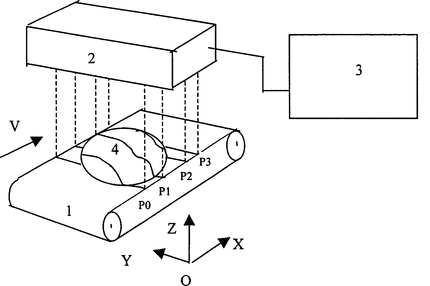
[0020] Such as figure 1 As shown, the measured object 4 is placed on the transmission device 1, and the three-dimensional measurement sensor array 2 is placed above the transmission device 1 and the measured object 4, and the image acquisition and processing device 3 receives the image measurement data sent by the three-dimensional measurement sensor array 2, and data processing. Method of the present invention is realized according to the following steps:
[0021] 1) The transmission device 1 has a measurement reference plane for placing the measured object, and can move the measured object 4 at a constant speed V;
[0022] 2) Install the three-dimensional measurement sensor array 2 above the transmission device to ensure that the optical axis of the light knife of the three-dimensional measurement sensor is perpendicular to the measurement reference plane...
PUM
 Abstract
Description
Claims
Application Information