Optical scanner

A scanner and optical technology, applied in the field of optical scanners, can solve problems such as the inability to ensure equidistant distance between the optical system and the scanned document, many assembly steps, and the guide rail is easy to fall.

Inactive Publication Date: 2004-02-11
UMAX DATA SYST
View PDF0 Cites 0 Cited by
  • Summary
  • Abstract
  • Description
  • Claims
  • Application Information

AI Technical Summary

Problems solved by technology

[0016] To sum up, the disadvantages of the known optical scanners are: many assembly tolerances, many assembly steps, easy drop of the guid

Method used


Image

  • Optical scanner
  • Optical scanner
  • Optical scanner

Examples


no. 1 example

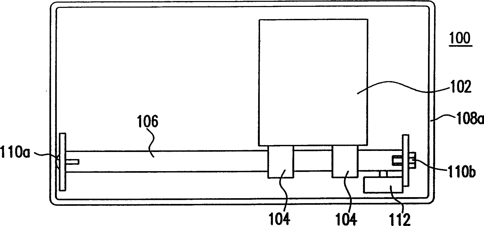
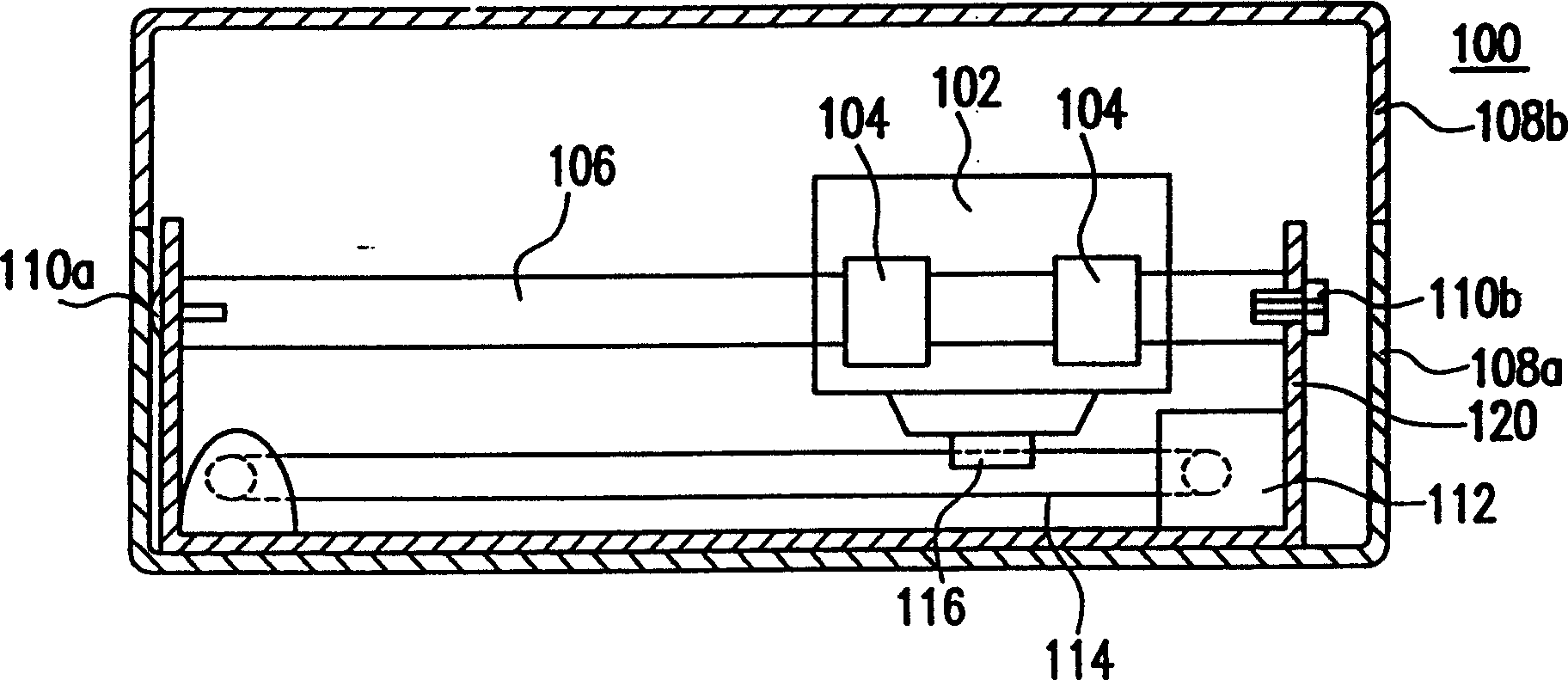
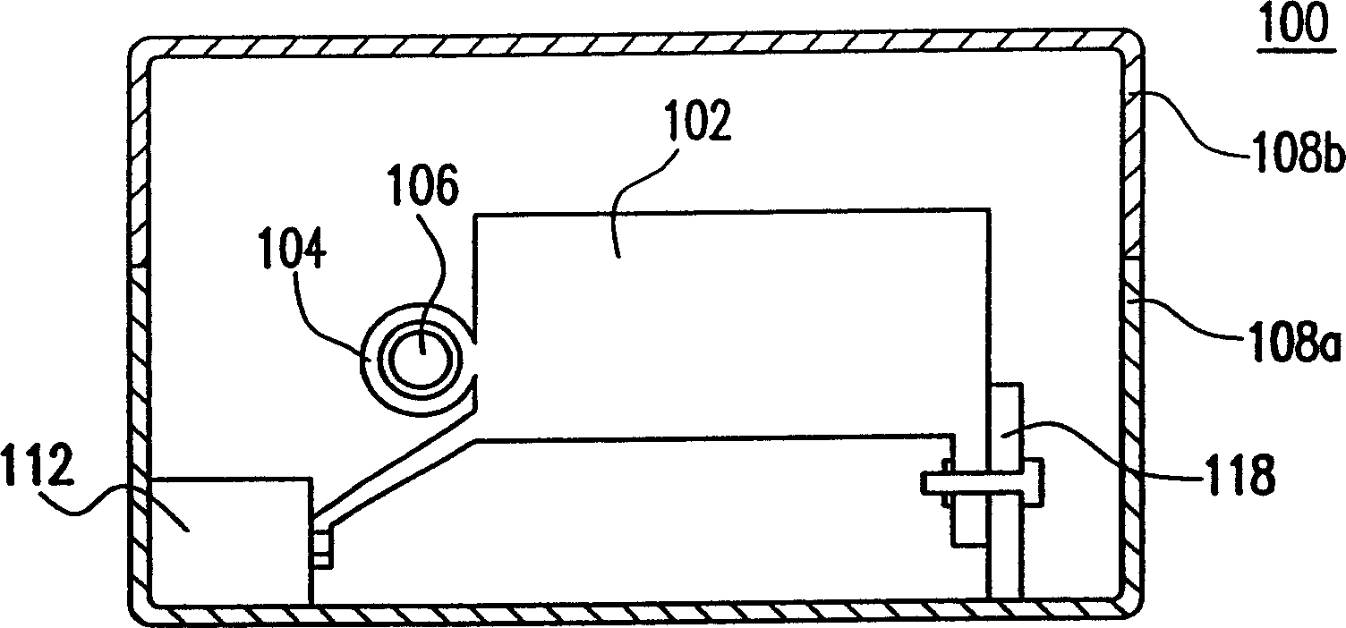
[0068] Please refer to Figure 4 , is a side sectional view of an optical scanner according to the first embodiment of the present invention.

[0069] The optical scanner 200 of the present invention includes: a carrier 202 , a casing 208 , a driving unit 212 and a transmission unit 214 . Wherein, the carrier 202 has a buckle 204, and an optical system (not shown in the figure) is arranged on the carrier 202 . The optical system at least includes: a reflection mirror group, a lens group and a photosensitive device. The photosensitive device includes a charge-coupled device and the like.

[0070] The casing 208 includes an upper casing 208 b and a lower casing 208 a, and the casing 208 has a guide rail 206 integrally formed inside the casing 208 . Moreover, the guide rail 206 has at least one buckle portion, preferably has two buckle portions 206 a, 206 b for buckling with the buckle sleeve 204 of the carrier 202 .

[0071] The driving unit 212 can be, for example, a motor....

no. 2 example

[0100] In addition to integrally forming the guide rail inside the casing as described in the first embodiment, the guide rail can also be formed separately and fixed on the inside of the casing.

[0101] Please also refer to Figure 18 and Figure 19 , are perspective schematic diagrams of a guide rail and its corresponding housing in the second embodiment of the present invention, respectively. In the second embodiment, except that the casing and the guide rail are different from the first embodiment, other components are the same as the first embodiment, and will not be repeated here.

[0102] The guide rail 256 has at least two seat buckles, preferably four seat buckles 274, and at least one sliding buckle, preferably two sliding buckles 256a, 256b. The seat buckle portions 274 are respectively used to engage with the fixing portions 276 of the housing 258 . The sliding buckle parts 256a, 256b are used to buckle with the buckle sleeve of the carrier.

[0103] Therefore...


PUM


Abstract

The optical scanner includes carrier, casing, driving unit and transmission unit. The carrier has one buckle and is provided with one optical system. The casing has one guide rail formed integrallyon the outside of the casing and with one buckled part for combination with the carrier. The transmission unit is connected to the driving unit and the carrier, so that the driving unit drives the transmission unit and thus the carrier and the carrier can slide along the guide rail via the buckled part and the buckle.

Description

technical field [0001] The present invention relates to an optical scanner, and in particular to an optical scanner which utilizes a fastening method to make a carrier slide along a guide rail. Background technique [0002] The principle of a general optical scanner (scanner) is to project a light source onto a scanned document, reflect the scanned document to a reflective lens group, and then image it on a charge-coupled device (CCD) through the lens group, and finally convert the received The image is converted into a digital signal for reading. The above-mentioned reflective mirror group, lens group and photosensitive device (ie, charge-coupled device) are generally collectively referred to as an optical system. [0003] In order to obtain a two-dimensional plane image, in addition to arranging the photosensitive devices along the horizontal direction, an optical scanner is usually equipped with a carriage on which an optical system is arranged, and the optical system is...

Claims


Application Information

Patent Timeline
IPC IPC(8): G06K9/20
Inventor 张文元曾仁寿
Owner UMAX DATA SYST
Why Eureka
Try Eureka