Power line transmission device

A transmission device and power line technology, applied in distribution line transmission system, output power conversion device, electrical components, etc., can solve the problems of using more power sources, high cost, and complicated wiring, so as to reduce power consumption and reduce wiring And erection cost, the effect of small size

Inactive Publication Date: 2004-03-03
CAMEO COMM
View PDF0 Cites 5 Cited by
  • Summary
  • Abstract
  • Description
  • Claims
  • Application Information

AI Technical Summary

Problems solved by technology

[0004] 1. Each device must be individually connected to the power supply
[0005] 2. Too many wires and complicated wiring
[0006] 3. Using to

Method used


Image

  • Power line transmission device
  • Power line transmission device
  • Power line transmission device

Examples


Embodiment Construction

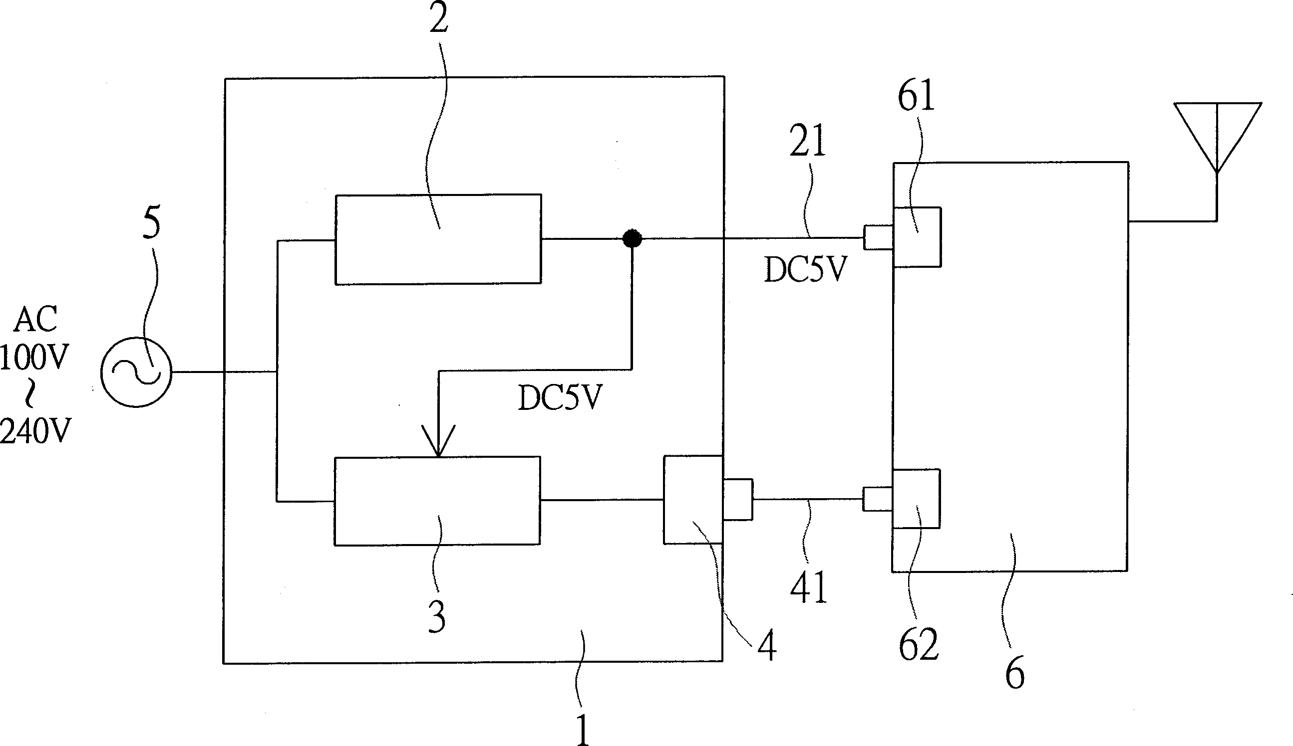
[0035] see figure 2 As shown; the present invention provides a power line transmission device, which mainly erects a power line transmission device 1 in the workplace; wherein, the power line transmission device 1 is composed of a switching power supply 2, a power line transmission Chip 3, an RJ-45 connector 4, a power connector 21 and a power plug 5 are combined; one end of the power line transmission device 1 is connected to the AC power supply (AC100V-240V) with the power plug 5, and the other end is connected with the The power connector 21 and the RJ-45 connector twisted pair 41 are connected to the RJ-45 connector 62 of the wireless network access device 6:

[0036] When the power plug 5 receives the AC power, it transmits the AC power to the switching power supply 2 and the power line transmission chip 3 respectively; and when the switching power supply 2 receives the AC power (AC110V-240V), With the conversion function of the switching power supply, the AC power sign...


PUM


Abstract

Exchange type power supplier and power line transmission chip are put in the power line transmission device. The one end of the device is connected to AC power, and the other end through power connecter and RJ-45 connecter twisted-pair is connected to wireless network accessor. When AC power signal being received through the plug, the signal is transferred to power supplier and transmission chip. The exchange type power supplier converts AC power to DC power, and the DC power is transferred to the transmission chip and the power socket of the wireless network accessor. With AC power signal being received, the transmission chip filters out data signal, which through RJ-45 connecter is transferred to the wireless network accessor. Thus, the power line transmission device and wireless network accessor share power source so as to lower cost. Data is transferred through power line in room so as to provide convenience and reduce wiring.

Description

technical field [0001] The invention relates to a power line transmission device. Background technique [0002] see figure 1 As shown; the power line transmission technology currently used in the industry is mainly to set up a power line transmission device A in the workplace, wherein the power line transmission device A is independently supplied with power by the power transformer A1, and the AC power (AC100V -240V) into DC power (DC5V), so that the power required by the power line transmission device A can be used for operation, and then the AC power signal is converted into a data signal by the power line transmission device A, and It is transmitted to the wireless network access device B through the signal line A2 for data transmission; and the wireless network access device B also needs to convert the AC power into a DC power supply (DC5V) through an independent power transformer B1 to For the power supply of the wireless network access device B, so that the wireless ...

Claims


Application Information

Patent Timeline
IPC IPC(8): H02M7/00H02M7/02H04B3/54
Inventor 高宪均
Owner CAMEO COMM
Why Eureka
Try Eureka