Method for exactly calibrating and modifying scanner by using normal scanner in precision measurement

A precision measurement and scanner technology, applied in the fields of instruments, character and pattern recognition, computer parts, etc., can solve problems such as difficult promotion, high price, distortion, etc.

Inactive Publication Date: 2004-03-24
NAT UNIV OF DEFENSE TECH
View PDF0 Cites 13 Cited by
  • Summary
  • Abstract
  • Description
  • Claims
  • Application Information

AI Technical Summary

Problems solved by technology

The geometric accuracy error of engineering measurement scanners used in fields such as geodetic surveying and mapping is generally about 2 to 5 microns, which can meet the requirements of high-precision engineering measurement, but the price is quite expe

Method used


Image

  • Method for exactly calibrating and modifying scanner by using normal scanner in precision measurement
  • Method for exactly calibrating and modifying scanner by using normal scanner in precision measurement
  • Method for exactly calibrating and modifying scanner by using normal scanner in precision measurement

Examples


Embodiment Construction

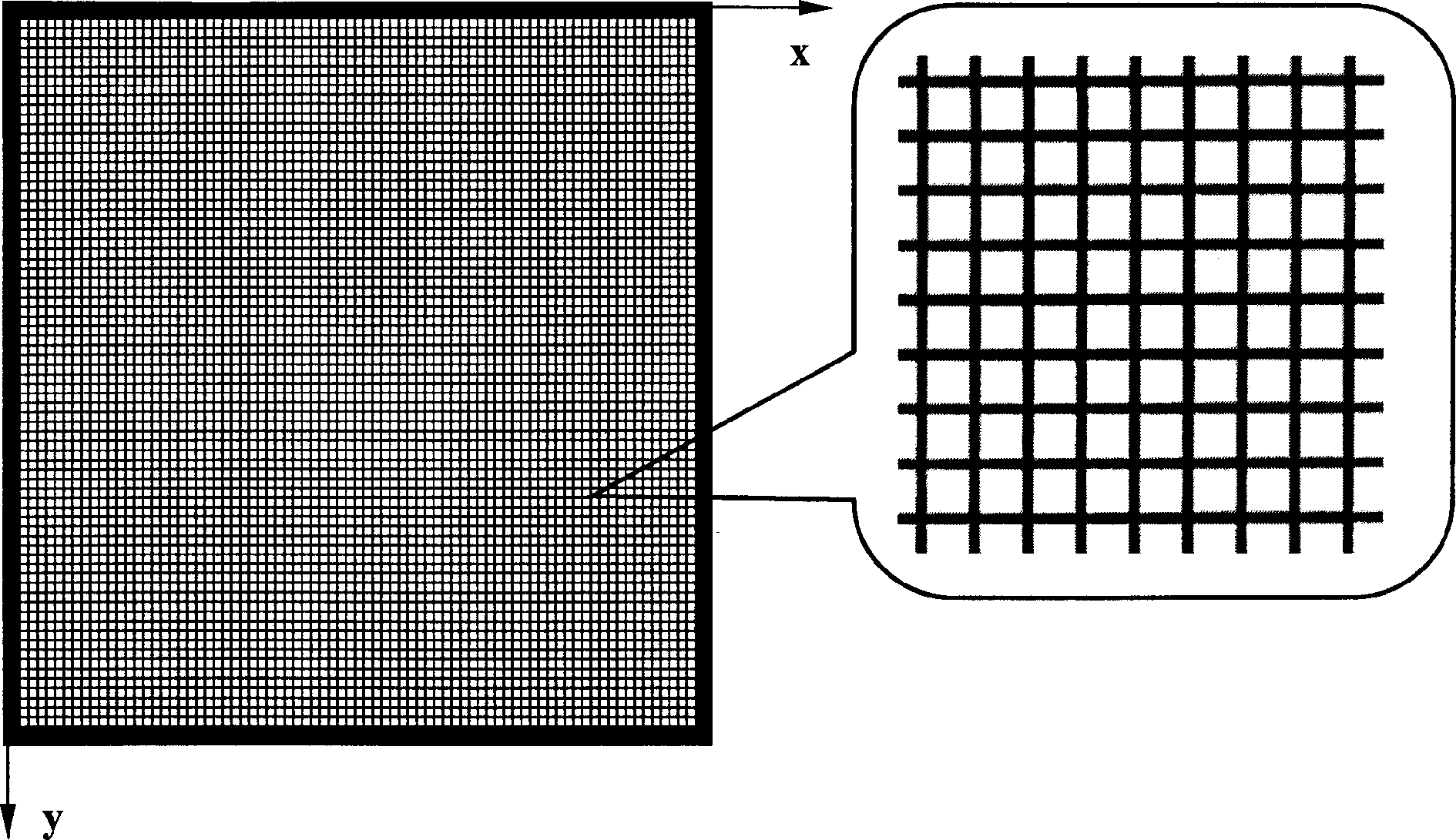
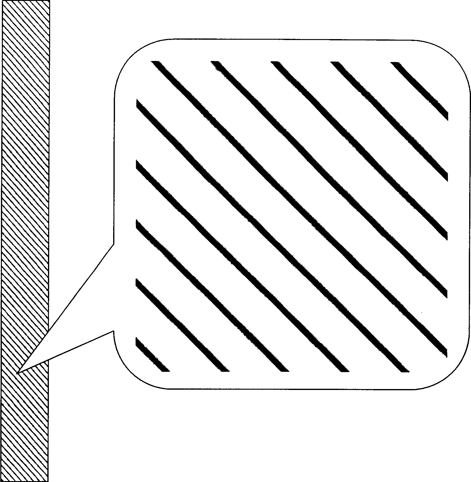
[0137] The measurement system is composed of ordinary flat-bed scanner, electronic computer, precise orthogonal grid and linear grid for calibration (or without linear grid), and application software developed on the basis of this calibration and correction method and digital image processing technology. Implement the described method as follows:

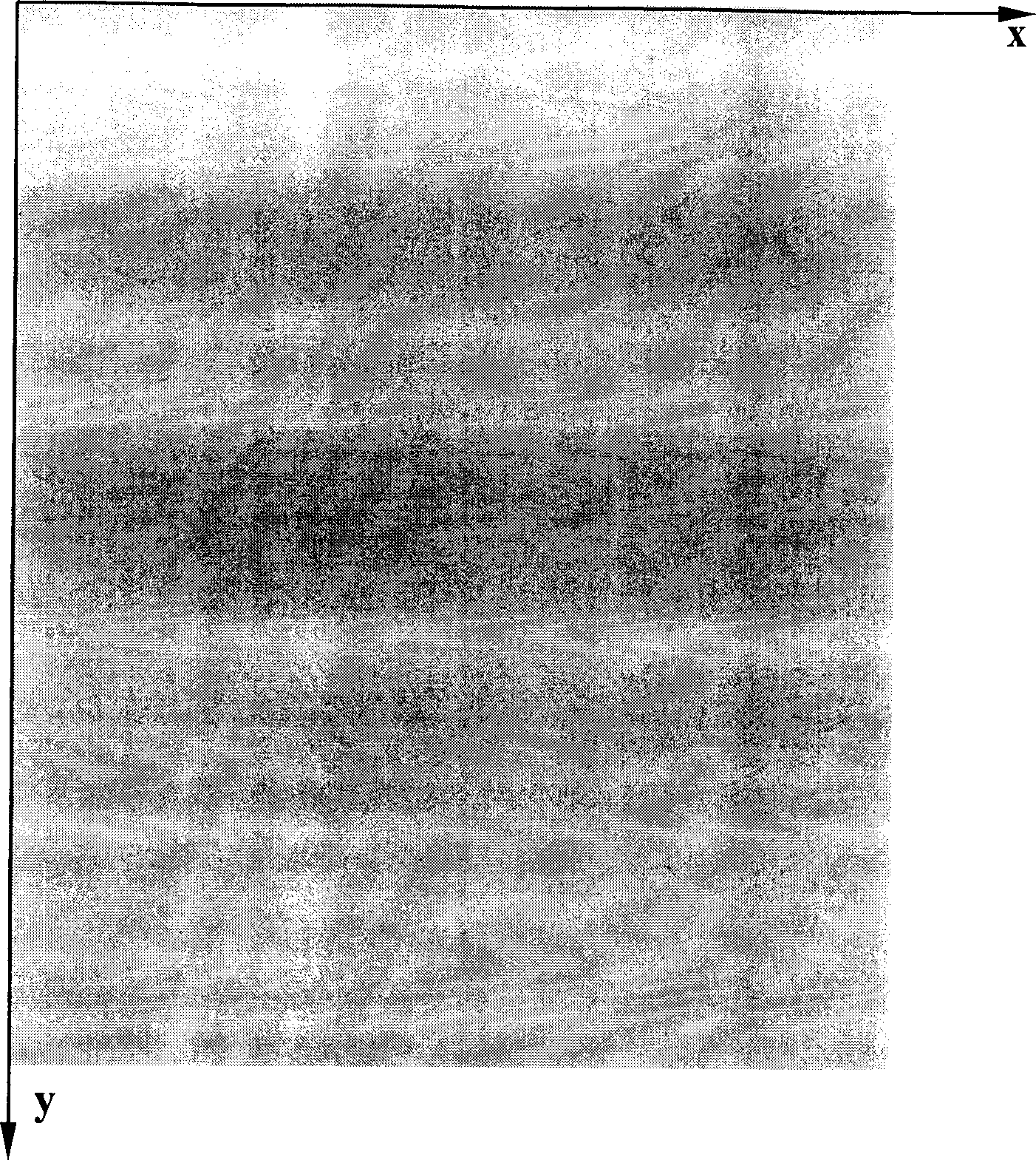
[0138] 1. Press the precision grid and linear grid (negligible) for the image to be tested and calibration Figure 4 or Figure 5 Arranged on the scanning platform;

[0139] 2. Scan the image to be tested and calibrate the precision grid and linear grid (negligible); for the scanned image obtained, selectively perform the following operations (generally applicable calibration and correction sequence):

[0140] 3.1 Calibrate and correct the Y-X error of the scanned image;

[0141] 3.2 Calibrate and correct the X-X error of the scanned image;

[0142] 3.3 Calibrate and correct the X-Y error of the scanned image;

[0143] 3.4 Cali...


PUM


Abstract

The method in the invention includes: a. arranges the image and the mark around the image on the platform of the scanner through precise orthogonal grid and precise linear grid, and defines the scanner line CCD direction is X direction, step motor is Y direction; b. carries on whole scan to the image and the mark through precise orthogonal grid and precise linear grid; c. marks and amends one or more sub-items error to the scanned image, the sub-items are X-X error, X-Y error, Y-Y error, Y-X error, lines proportion error, row proportion error, vertical and horizontal proportion error, scanning error and high frequency vibration error.

Description

technical field [0001] The present invention relates to precision optical measurement technology, and further refers to a method for accurately demarcating and correcting scanned images of ordinary flat-panel scanners. Background technique [0002] The use of digital image processing technology for precision optical measurement has the characteristics of fast speed, high precision, high degree of automation, and full-field measurement. But in many cases, the objects to be measured are recorded on photosensitive media such as large-format films and dry plates. In order to use digital image processing technology to measure them, they must be digitized. If the size of the image to be measured is large, the resolution of the general area array CCD cannot meet the requirements of precise measurement; while the flatbed scanner using the linear array CCD imaging can achieve very high resolution. The geometric accuracy error of engineering surveying scanners used in fields such as ...

Claims


Application Information

Patent Timeline
IPC IPC(8): G06K9/03
Inventor 于起峰尚洋陆宏伟孙祥一
Owner NAT UNIV OF DEFENSE TECH
Why Eureka
Try Eureka