
Lifting/lowering type substrate proless device and substrate process system having same

A substrate processing device and lift-type technology, which is applied in the directions of optics, instruments, electrical components, etc., can solve the problems of processing liquid, container enlargement, surface dry spots, etc., and achieve the effect of high-precision control and easy speed control

Inactive Publication Date: 2004-03-24
SUMITOMO PRECISION PROD CO LTD
View PDF0 Cites 12 Cited by
  • Summary
  • Abstract
  • Description
  • Claims
  • Application Information

AI Technical Summary

Problems solved by technology

[0014] That is, for example, such as Figure 15 As in the example shown, if the substrate K is etched in the first processing unit 206 and then transferred without being cleaned, the degree of etching progress will be affected by the difference in the transfer time to the second processing unit 207. Different, cannot control etching with high precision
Since the substrate conveying unit 210 has a complicated operation mechanism consisting of a mechanism for raising and lowering the substrate K and a mechanism for moving the second conveying roller 216, it is difficult to control the conveying time with high precision.
[0015] In addition, for example, when the final process of the first processing unit 206 is a cleaning process, if the substrate K is conveyed without drying, dry spots or stains will occur on the surface, and the substrate K will become a defective product.
[0016] Furthermore, in the above-mentioned conventional substrate processing system 200, various processing liquids such as etching liquid and cleaning water are supplied to the substrate K while the substrate K in a horizontally supported state is conveyed in the horizontal direction, but there are the following problems That is, when the processing liquid is supplied to the substrate K in a horizontal posture in this way, it is difficult to generate a liquid flow of the processing liquid on the surface of the substrate K, and the initially supplied processing liquid stays on the surface of the substrate K, so it is difficult to replace the continuous substrate K. The supply of new treatment liquid takes time for treatment, and uniform treatment cannot be performed
[0017] On the other hand, if a large amount of processing liquid is supplied to the substrate K, although the replaceability of the processing liquid can be improved, the efficiency is poor if a large amount of processing liquid is used. change
[0018] In addition, in the above-mentioned conventional substrate processing system 200, since the two processing lines of the first processing unit 206 and the second processing unit 207 are arranged in parallel, there is also a problem that the installation efficiency of the equipment is poor.

Method used


Image

  • Lifting/lowering type substrate proless device and substrate process system having same
  • Lifting/lowering type substrate proless device and substrate process system having same
  • Lifting/lowering type substrate proless device and substrate process system having same

Examples


Embodiment Construction

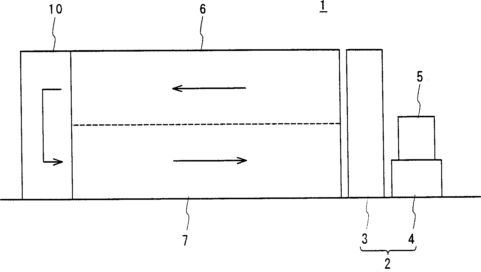
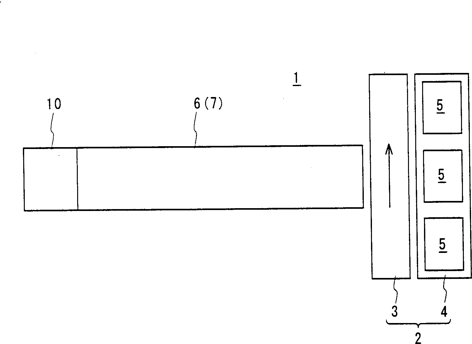
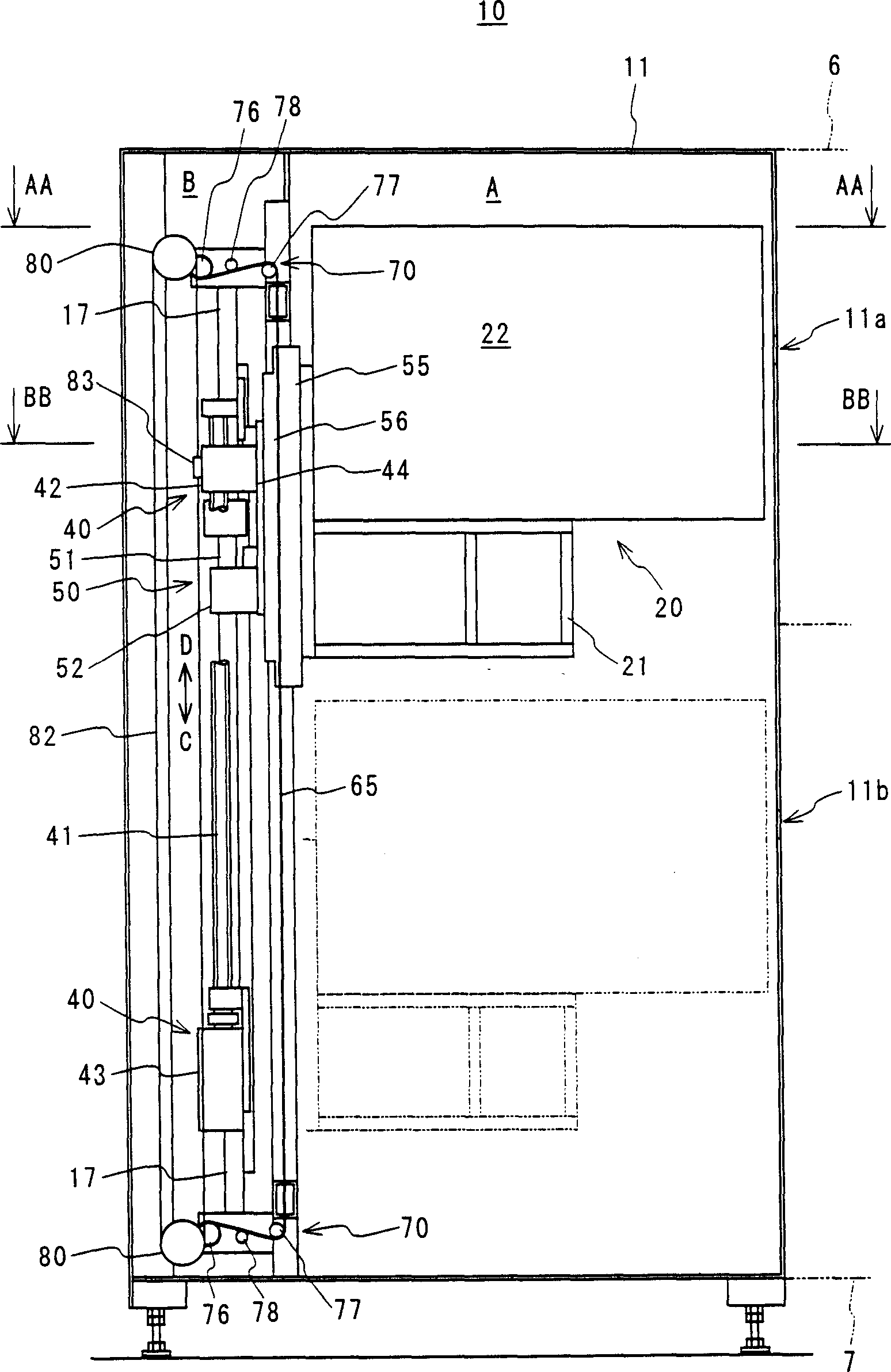
[0069] The following describes specific embodiments of the present invention according to the accompanying drawings. figure 1 is a front view showing a basic configuration of a substrate processing system according to an embodiment of the present invention, figure 2 is its floor plan. in addition, image 3 is a front cross-sectional view showing the basic configuration of the lift-type substrate processing apparatus according to this embodiment, Figure 4 is a front cross-sectional view showing the basic configuration of the cleaning device of this embodiment, Figure 5 is its side sectional view. in addition, Figure 6 is along Figure 5 Plane sectional view of the CC-CC direction in, Figure 7 is along image 3 Plane sectional view of AA-AA direction in, Figure 8 is along image 3 Plane sectional view of BB-BB direction in . also, image 3 also along Figure 7 The sectional view of the DD-DD direction in .

[0070] First, the configuration of the substrate pr...


PUM


Abstract

The substrate treatment apparatus 10 includes a housing shape cover 11 having a substrate input port 11a and a substrate discharge port 11b provided in parallel in a vertical direction, and a treatment mechanism 20 mounted in the cover 11. The apparatus 10 further includes the treatment mechanism 20 having a conveying / supporting means for receiving and supporting the substrate conveyed from the input port 11a and discharging the substrate from the port 11b, a support substrate 21 for supporting the conveying / supporting means, a substrate inclining means for inclining the substrate supported by the conveying / supporting means, and a treatment fluid discharge means arranged above the substrate / supporting means to discharge a treatment fluid on the substrate inclined by the substrate inclining means, and a lifting means 40 for supporting the treatment mechanism 20, lifting the treatment mechanism 20 in a vertical direction and making the treatment mechanism 20 pass via the port 11a and the port 11b.

Description

technical field [0001] The present invention relates to a processing device and multi-connection device for performing predetermined processing on various substrates such as semiconductor (silicon) wafers, liquid crystal glass substrates, glass substrates for photomasks, substrates for optical discs, etc., while moving (transporting) them. A substrate processing system composed of a processing device. Background technique [0002] For example, in the manufacturing process of liquid crystal glass substrates, wet processing of coating of developing solution, coating of etchant, and coating of stripping liquid for stripping resist film is carried out, and cleaning is performed during each wet processing. Net treatment and dry treatment. [0003] In addition, as a processing apparatus used for each of the above-mentioned processings, a processing apparatus configured in such a manner that a substrate is placed on a conveying roller and passed through the conveying roller while ...

Claims


Application Information

Patent Timeline
IPC IPC(8): H01L21/68G02F1/13H01L21/00
CPCH01L21/67017H01L21/68742
Inventor 水川茂中田胜利
Owner SUMITOMO PRECISION PROD CO LTD
Learn More